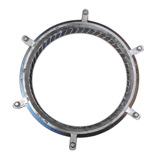
Designing robust electric motor rotors and housings is no longer just about electromagnetic performance. As power density and efficiency targets rise, your choice of aluminium die casting process, tooling, and supplier can make or break a motor program’s cost, reliability, and launch schedule.
This guide explains how aluminium die casting actually works for electric motor rotors and housings, what capabilities and constraints you should design around, and which quality controls matter most if you want consistent performance in the field.
We will walk through process fundamentals, design-for-manufacturability (DFM) guidelines, common die casting defects, and how integrated stamping–die casting–machining suppliers like ASA Industries can de-risk your supply chain.
For a deeper dive into how tooling influences manufacturability and cost across both stamping and casting, see our guide on tooling design for stamping and die casting.
What is aluminium die casting in the context of electric motors?
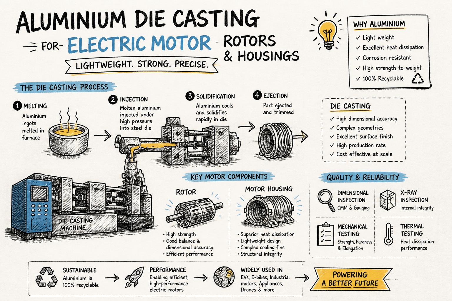
Aluminium die casting is a high-pressure process where molten aluminium is injected into a steel die cavity, rapidly solidifies, and is ejected as a near-net-shape component. For electric motors, it is most commonly used for:
Die cast rotors for induction, universal, shaded pole, and some BLDC designs
Motor housing casting and end shields that provide structural support and thermal management
Mounting brackets and other structural components integrated with the motor assembly
Compared with sand casting or gravity casting, high-pressure aluminium die casting offers:
Higher production rates and lower cost per part at volume
Better dimensional accuracy and surface finish
Ability to integrate ribs, bosses, and complex features directly into the casting
For rotors, die casting also ensures good electrical contact between the aluminium cage and the rotor laminations, which is critical for efficiency and starting torque. We compare this in detail in our article on die-cast rotors versus fabricated rotors.
Key advantages of aluminium die casting for rotors and housings
1. Lightweight with good thermal conductivity
Aluminium’s low density helps reduce motor weight, which is especially valuable in appliances, HVAC, and automotive applications. At the same time, aluminium’s high thermal conductivity helps transfer heat from windings and cores to the housing and then to ambient.
For housings, this allows you to design integrated cooling fins and ribs that are cast in one shot, rather than machining them later.
2. High productivity and repeatability
Once the die is validated, high-pressure die casting can produce thousands of parts per shift with consistent dimensions. For OEMs, this means:
Stable process capability (Cp, Cpk) on critical dimensions
Predictable takt times that align with assembly lines
Lower labour content per part compared with slower processes
3. Design freedom for integrated features
With the right tooling, aluminium die casting allows you to integrate:
Mounting feet and brackets
Cooling fins and air channels
Bosses for bearings, sensors, and fasteners
Internal passages for cable routing or airflow
Each integrated feature you cast instead of machining or welding reduces part count, assembly time, and tolerance stack-up.
4. Good balance of mechanical and electrical performance
For induction rotors, aluminium die casting creates a solid cage with end rings that are metallurgically bonded to the rotor bars. This offers:
Low electrical resistance for good efficiency
Mechanical robustness at high speeds
Consistent performance from rotor to rotor
According to research on motor efficiency improvements, optimising rotor design and materials can contribute significantly to overall motor efficiency gains, especially in high-duty-cycle applications.
Locking capacity and part size: what can you realistically cast?
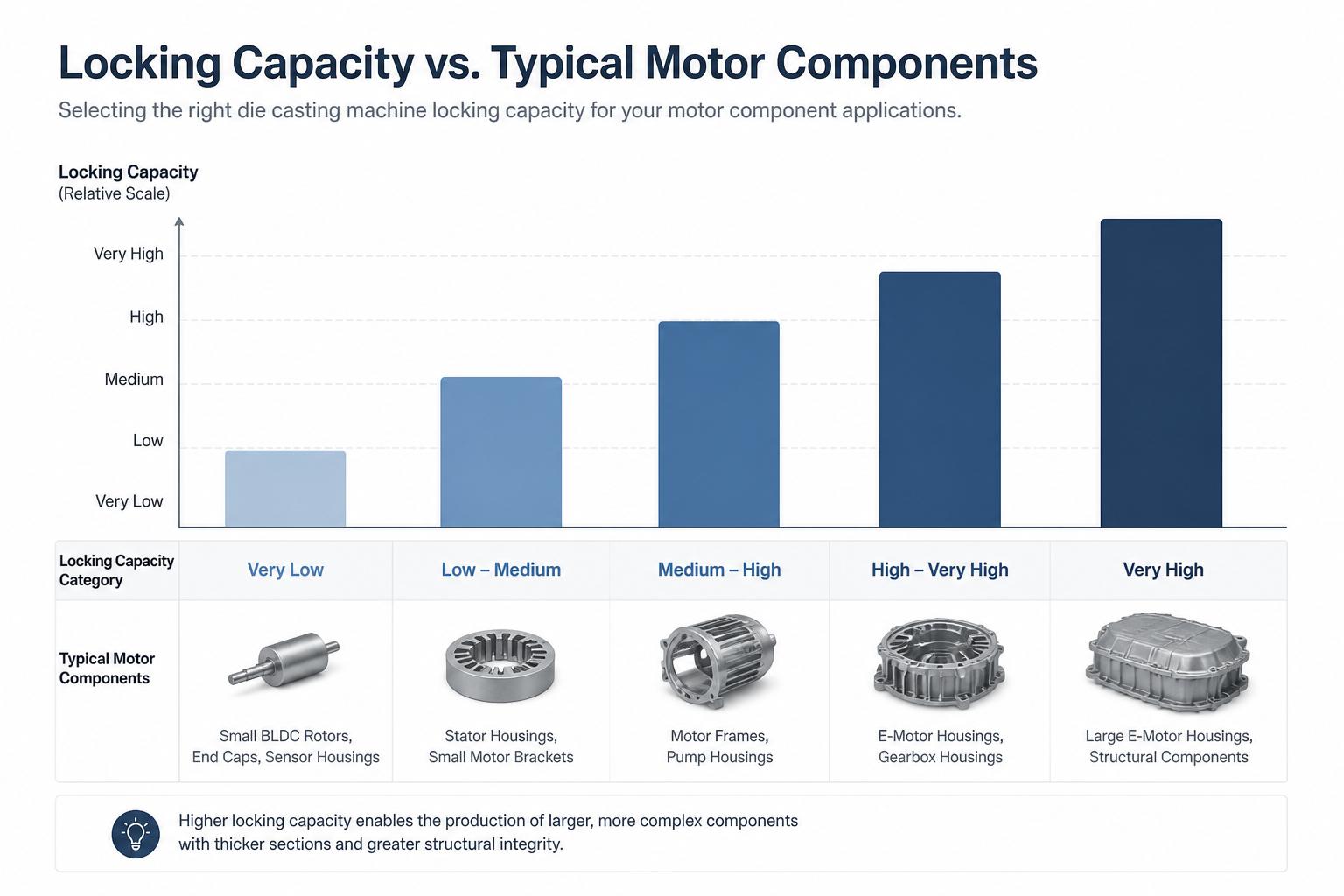
One of the first constraints you must understand is the locking capacity (clamping force) of the die casting machine. This determines the maximum projected area and complexity of the part you can cast without flash or dimensional instability.
At ASA Industries, our aluminium die casting machines operate in the 80–250 Ton locking capacity range. Practically, this covers:
Small to medium die cast rotors for single-phase induction, universal, BLDC, and shaded pole motors
Compact motor housing castings and end shields for household and light industrial applications
Medium-sized brackets and structural components associated with motor assemblies
When you share a new design with a die casting manufacturer, it helps to provide:
2D drawings with projected area indicated
3D models (STEP/IGES) for accurate fill and solidification analysis
Expected annual volumes and ramp-up plans
This allows the supplier to confirm if their locking capacity is suitable and whether multi-cavity tooling is feasible.
Material choices: which aluminium alloys work best?
Most motor rotors and housings use standard high-pressure die casting alloys such as Al-Si or Al-Si-Cu compositions, which offer a good balance of castability, mechanical properties, and cost.
Key properties you should consider include:
Fluidity for thin sections and complex geometries
Thermal conductivity for housings and cooling fins
Mechanical strength and fatigue resistance for rotating parts and mounting features
Corrosion resistance in humid or chemically aggressive environments
Standards such as ASTM specifications for aluminium casting alloys provide typical property ranges and composition limits. Your supplier should be able to recommend alloys based on your performance requirements and downstream processes (e.g., machining, coating, impregnation).
How aluminium die casting of rotors works in practice
For electric motor rotors, the aluminium die casting process must not only fill the die, but also penetrate and bond with the rotor laminations.
1. Rotor stack preparation
Rotor laminations are stamped from electrical steel and stacked to the specified length, often using interlocking features or welding. As a stamping-focused manufacturer, ASA Industries supplies rotor and stator laminations as well as die-cast rotors, which simplifies supply chains for OEMs. Learn more about the upstream stamping side in our article on integrated stamping, die casting, and machining supply chains.
2. Loading into the die
The rotor stack is loaded into the die cavity, either manually or via automation. The die is designed so that the aluminium will flow through the rotor slots to form the cage bars and end rings.
3. Injection and solidification
Molten aluminium is injected at high pressure, filling the die and rotor slots in milliseconds. Proper gating and venting design are critical to avoid air entrapment, misruns, and cold shuts.
Cooling channels within the die control solidification speed to minimise internal stresses and porosity.
4. Ejection and trimming
After solidification, the die opens and ejector pins push out the rotor. Runners, overflows, and flash are trimmed, and the rotor moves to subsequent operations such as machining, balancing, and surge testing (for electrical integrity).
We cover these downstream checks in more detail in our guide to quality controls in die casting.
How aluminium die casting of housings differs from rotors
While the basic process is the same, motor housings have different design and process considerations than rotors.
1. Wall thickness and rib design
Housings often have larger, more complex geometries with varying wall thicknesses. You should aim for:
Uniform wall thickness where possible to reduce warpage and porosity
Ribs instead of thick sections to achieve stiffness without sink defects
Generous radii at junctions to improve flow and reduce stress concentrations
2. Tolerance strategy
Critical bearing bores, mounting faces, and sealing surfaces are usually machined after casting. Design your drawing with:
As-cast tolerances for non-critical surfaces
Machining stock on critical surfaces, clearly indicated
Datum structure aligned with how the part will be fixtured for machining and assembly
3. Integration with other components
Housings often interface with stamped stators, end shields, and covers. Working with a supplier that provides both electrical stampings and aluminium die casting simplifies tolerance coordination and reduces the risk of misalignment at assembly.
Design-for-manufacturability (DFM) guidelines for aluminium die casting
Good DFM can dramatically reduce die iterations, scrap, and total landed cost. Below are practical guidelines specifically for motor rotors and housings.
1. Wall thickness and transitions
Maintain a minimum wall thickness that matches your supplier’s capability (often 2.0–3.0 mm for standard die casting alloys, depending on flow length).
Avoid sudden thickness changes; use tapers or fillets to transition between sections.
Use coring to hollow out massive sections instead of casting them solid.
2. Draft angles
Provide adequate draft (typically 1–3°) on external and internal walls aligned with the die opening direction.
Increase draft on deep pockets or textured surfaces.
Discuss draft standards early with your die casting manufacturer to avoid late design changes.
3. Gating, overflows, and vents
While gating is primarily a tooling responsibility, your part design should leave enough real estate for gates, runners, and vents. Poor venting is a root cause of several die casting defects such as porosity and cold shuts.
Collaborate on a joint DFM review where your supplier can suggest minor changes (e.g., adding pads or thickening local areas) to improve filling and venting.
4. Tolerances and GD&T
Use realistic as-cast tolerances based on process capability data rather than machining-level tolerances everywhere.
Reserve tight tolerances for features that truly affect performance or assembly.
Apply GD&T (position, flatness, concentricity) thoughtfully, aligned with how the part is located and clamped in real fixtures.
5. Consider downstream processes
Think beyond casting:
Design machining datums that are accessible and robust.
Allow space for cutting tools and probes.
Plan for coatings, impregnation, or surface treatments that may affect clearances.
Common aluminium die casting defects in rotors and housings
Understanding typical defects helps you write better specifications and evaluate suppliers more effectively.
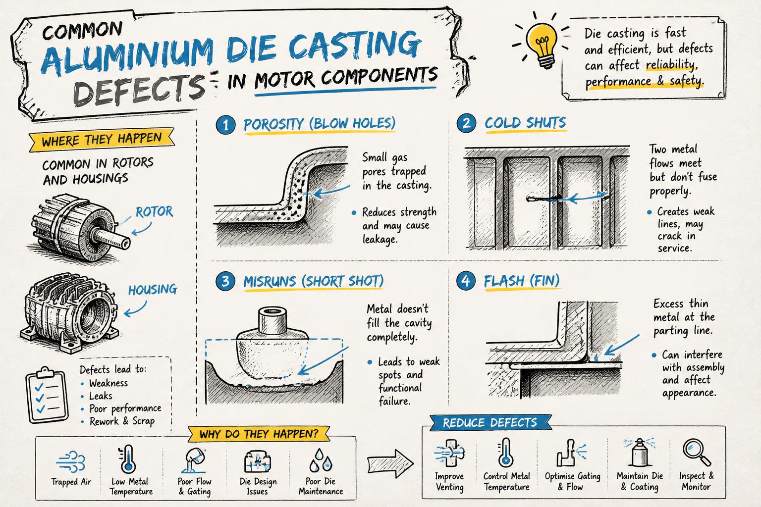
1. Porosity
Gas porosity and shrinkage porosity are small voids inside the casting. In rotors, excessive porosity can increase resistance and reduce mechanical strength. In housings, it can cause leakage or weaken mounting features.
Root causes include trapped air, inadequate venting, poor gating design, or improper melt handling. Process controls and proper die maintenance are essential to keep porosity within acceptable limits.
2. Cold shuts and misruns
Cold shuts occur when two metal fronts meet but do not fully fuse, leaving a visible line or weak interface. Misruns are regions where the metal did not fill completely.
These defects often result from low metal temperature, insufficient injection speed, or poor gating. They are particularly critical in rotor bars and end rings, where continuity of the aluminium path is essential for electrical performance.
3. Flash
Flash is thin excess metal at the parting line or around ejector pins. While often removable by trimming, excessive flash indicates issues with locking capacity, die wear, or incorrect process parameters.
In rotors, uncontrolled flash at the end rings can affect balance and may interfere with downstream operations.
4. Dimensional instability and warpage
Uneven cooling, thick sections, or poor die temperature control can cause warpage and dimensional variation. For housings, this can lead to misalignment of bearing seats and stator bores, increasing noise and reducing efficiency.
Designing for uniform wall thickness and working with a supplier that controls die temperature and process parameters tightly is key.
Critical quality controls for die-cast rotors and housings
For motor applications, quality is not just about appearance; it directly impacts efficiency, noise, and lifetime. A robust die casting manufacturer should have layered controls from incoming material to final testing.
1. Incoming material inspection
Chemical composition checks of aluminium ingots and returns
Cleanliness and coating condition of rotor and stator laminations
Verification of any inserts or hardware used in housings
2. In-process controls
Monitoring melt temperature, die temperature, and injection parameters
SPC on critical dimensions (e.g., rotor OD, end ring thickness, housing bore locations)
Regular die maintenance and cleaning to prevent build-up and wear
3. Visual and dimensional inspection
Visual checks identify surface defects, incomplete fill, and excessive flash. Dimensional inspection—using gauges, CMM, or dedicated fixtures—verifies that key dimensions and GD&T requirements are met.
For more detail on how to structure these checks across tooling, casting, and final testing, see our article on quality controls in die casting.
4. Non-destructive and functional testing
Depending on your application and risk profile, you may specify:
X-ray or CT sampling to monitor internal porosity and defects
Helium or air leak testing for housings that must be pressure-tight
Electrical tests such as surge testing for die-cast rotors to detect shorted turns or discontinuities
Standards from organisations like IEEE and IEC often guide test methods and acceptance criteria for motor performance and insulation systems.
Why integrated stamping, die casting, and machining matters
Many motor OEMs still source laminations, die-cast rotors, housings, and machining from separate vendors. This increases coordination effort, tolerance risk, and lead time.
Working with an integrated supplier that combines electrical stamping, aluminium die casting, and CNC turning can help you:
Align stack tolerances between laminations and die-cast rotors
Optimise housing designs for both casting and machining in one DFM loop
Reduce logistics and inventory between multiple operations
Shorten development cycles from prototype to SOP
We explore these benefits in more depth in our article on integrating stamping, die casting, and machining in your motor component supply chain.
How to specify aluminium die casting requirements to your supplier
Clear, structured specifications set the foundation for a successful project. When engaging a die casting partner for rotors or housings, make sure you cover the following.
1. Part and performance requirements
3D models and fully-dimensioned 2D drawings with GD&T
Material specification (alloy, temper, any special requirements)
Mechanical, thermal, and electrical performance targets
Environmental and regulatory requirements (e.g., corrosion, RoHS)
2. Production and quality expectations
Annual and peak monthly volumes, expected ramp-up curve
Packed part weight and scrap targets
Sampling and PPAP expectations
Required test coverage (e.g., 100% surge testing for rotors, leak testing for housings)
3. Tooling and change management
Ownership and maintenance responsibility for tooling
Expected tool life and spare insert strategy
Process for engineering changes and revision control
Early technical workshops and DFM reviews will help avoid surprises later, especially around locking capacity, gating layout, and achievable tolerances. Our article on tooling design for stamping and die casting outlines what OEM engineers should expect from this collaboration.
When aluminium die casting is the right choice—and when it is not
Aluminium die casting is powerful, but not always the best solution. Consider it the preferred option when you need:
Medium to high volumes with stable demand
Complex geometries with integrated features
Good surface finish and dimensional repeatability
Lightweight components with reasonable mechanical strength
Alternative processes may be better when you have:
Very low volumes or frequent design changes (consider sand casting or machining from solid)
Extremely high mechanical strength requirements (for some high-speed rotors, alternative materials or fabrication methods may be preferred)
Very large housings beyond available locking capacity
For rotors specifically, our comparison of die-cast versus fabricated rotors can help you decide which route is best for your motor program.
How ASA Industries supports aluminium die casting for electric motors
ASA Industries has been supplying electric motor components since 1985, with a focus on electrical stamping, die cast rotors, and precision sheet metal components. Our aluminium die casting capabilities include:
High-pressure die casting machines with 80–250 Ton locking capacity
In-house precision tooling design, manufacturing, and maintenance
Integrated stamping for rotor and stator laminations, plus annealing and Epstein testing
CNC turning and machining for critical housing and rotor features
ISO-certified quality systems with SPC, incoming and final inspection, and surge testing for rotors
By combining stamping, die casting, and machining under one roof, we help OEMs reduce risk, lead time, and total cost while meeting demanding performance and reliability targets.
Next steps: making aluminium die casting work for your next motor program
To move from concept to a robust, manufacturable design for your rotors and housings:
Define clear performance requirements—mechanical, electrical, and thermal—for your motor.
Engage your aluminium die casting partner early with 3D models and preliminary drawings.
Conduct joint DFM and tooling reviews focusing on locking capacity, wall thickness, gating, and tolerances.
Agree on a quality plan that covers material control, in-process monitoring, inspection, and functional testing.
Prototype, validate, and iterate quickly with an integrated supplier who can support stamping, casting, machining, and testing.
If you are planning a new motor platform or looking to localise your supply chain, ASA Industries can help you evaluate whether aluminium die casting is the right fit for your rotors and housings, and how to design for reliable, cost-effective production from day one.