When a motor platform misses its efficiency or noise targets, the root cause is often buried deep in the rotor and stator lamination stacks. By the time the problem shows up in test benches or the field, fixing it means redesigns, new tooling, and lost months.
This explainer walks through how rotor and stator lamination stacks are built, how different stacking and bonding methods behave in the real world, and what to watch in your specifications and supplier discussions. The goal: help motor and appliance OEMs make better upfront decisions so the next platform hits performance and cost targets without surprises.
We will focus on practical trade-offs-core loss, noise and vibration, mechanical robustness, manufacturability, and cost-drawing on how high-volume suppliers like ASA Industries approach electrical stamping and magnetic core manufacturing for appliance and industrial applications.
What are rotor and stator lamination stacks?
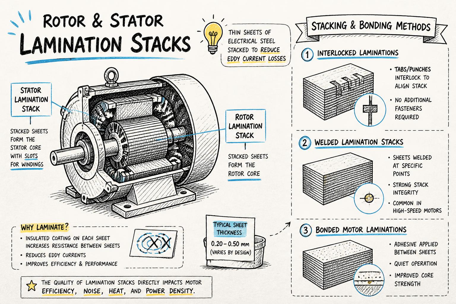
At the simplest level, a lamination stack is a column of thin, punched electrical steel sheets (laminations) that form the magnetic core of a motor’s rotor or stator. Instead of using a solid steel core, OEMs use laminations to reduce eddy current losses and heating at AC frequencies.
Each lamination is coated with a thin insulating layer (inorganic, organic, or hybrid) so that, when stacked, the electrical resistance between sheets is high. This is a fundamental lever for reducing core loss in lamination stacks, especially at higher switching frequencies in BLDC and high-efficiency induction motors.
Key functions of lamination stacks
Guide magnetic flux: Provide a low-reluctance path for the motor’s magnetic circuit.
Support conductors: House stator windings or rotor bars (die-cast or inserted).
Provide mechanical integrity: Withstand centrifugal forces, thermal cycling, and assembly loads.
Influence noise and vibration: Stack stiffness, bonding, and geometry affect acoustic signatures.
How you specify, stack, and bond these laminations directly affects efficiency, torque ripple, noise, and long-term reliability.
Core loss in lamination stacks: why stacking choices matter
Core loss in rotor and stator lamination stacks has three main components: hysteresis loss, eddy current loss, and, in practice, additional losses from manufacturing damage (burrs, residual stress, poor insulation, etc.).
According to IEC and IEEE standards and typical data from electrical steel suppliers like Nippon Steel and ArcelorMittal, manufacturing-related factors can add several percent to the nominal loss values measured on pristine steel samples. That difference often comes from how laminations are stamped, stacked, bonded, and annealed, not just from the grade of steel itself.
How stacking influences core loss
Interlaminar insulation quality: Scratched or crushed coatings during stacking create low-resistance bridges between sheets, increasing eddy currents.
Residual stress: Aggressive interlocking, welding, or poor stamping can increase local stress, raising hysteresis loss.
Air gaps and voids: Uneven stacking or poor bonding creates local flux crowding and hot spots.
Post-processing (annealing): Proper annealing can relieve stresses from stamping and stacking, restoring magnetic properties closer to steel datasheet values.
For high-efficiency or premium motors, you cannot treat stacking and bonding as a secondary detail. They are part of the electromagnetic design.
Lamination stacking methods: overview and trade-offs
Most rotor and stator cores in volume production use one of four main lamination stacking methods:
Each method has different implications for cost, throughput, noise, and efficiency.
1. Loose stacking with external clamping
How it works: Individual laminations are stacked in a fixture or on a mandrel. The stack is then held together mechanically using rivets, bolts, end plates, or banding—often combined with the motor housing or rotor cage.
Pros:
Simple process and tooling.
Minimal impact on steel properties (no welding heat-affected zones).
Easy to rework or disassemble in development phases.
Cons:
Risk of lamination movement or "rattle" if clamping is insufficient.
Potential for increased noise and vibration.
Extra parts (fasteners, end plates) and assembly steps add cost for high-volume programs.
Best suited for: Prototypes, low-volume industrial motors, or designs where mechanical clamping is already provided by another component.
2. Interlocked laminations
How it works: During stamping, small tabs and slots are formed in the lamination. When stacked, these features deform and lock successive laminations together. This is one of the most common methods for appliance and small motor stators.
Pros:
High-speed, automated stacking directly from progressive die stamping.
No additional materials (adhesive, weld wire) required.
Good dimensional consistency when tooling is well-maintained.
Cons:
Local plastic deformation can increase residual stress and core loss.
Tabs slightly reduce effective cross-section and can affect flux distribution.
Improper interlock design can lead to stack looseness or distortion.
Best suited for: High-volume stator cores in single phase induction motors, universal motors, and shaded pole motors where cost and throughput are critical and efficiency targets are moderate to high.
3. Welded lamination stacks
How it works: After stacking, the outer diameter (OD), inner diameter (ID), or end faces of the stack are joined using spot welding, projection welding, or seam welding. Welded lamination stacks are common for larger industrial motors and rotors where high mechanical strength is needed.
Pros:
Very robust mechanical connection, suitable for high-speed rotors.
Good control of stack height and squareness when fixtured correctly.
Compatible with a wide range of lamination sizes and geometries.
Cons:
Heat-affected zones can degrade local magnetic properties and increase loss.
Risk of shorting the interlaminar insulation near welds, raising eddy currents.
Additional process step, equipment, and quality controls required.
Best suited for: Medium to large industrial motors, traction motors, and rotors where mechanical integrity under high centrifugal loads is a priority.
4. Bonded motor laminations
How it works: A thin adhesive layer is applied between laminations, typically via bonding varnish or pre-coated steel. Stacks are then cured under temperature and pressure, forming a monolithic, rigid core.
Pros:
Excellent damping of vibration and acoustic noise.
Very uniform stack with minimal air gaps and high dimensional stability.
Potentially lower core loss due to better insulation and reduced movement.
Cons:
Adhesive and curing add material and process cost.
Requires tight process control for bond thickness and cure profile.
Rework is difficult or impossible once cured.
Best suited for: High-efficiency BLDC motors, premium appliance motors, and applications with stringent noise limits (HVAC, automotive, high-end consumer products).
Comparing lamination stacking methods: core loss, noise, and cost
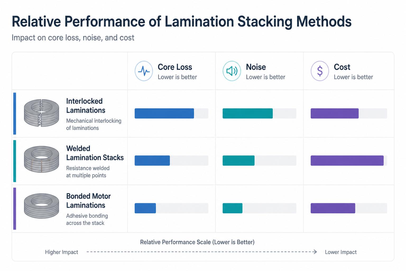
Every OEM will weigh these factors differently, but the relative trends across methods are consistent:
Core loss: Bonded stacks typically offer the lowest additional loss beyond the steel datasheet, followed by well-executed interlocked stacks. Welded stacks can show localized higher loss near welds unless carefully optimized.
Noise and vibration: Bonded stacks provide the best damping, welded stacks are stiff but can transmit vibration, and loose or poorly interlocked stacks are most prone to lamination buzz.
Cost and throughput: Interlocked laminations usually win for high-volume appliance motors due to integration with progressive die stamping. Bonded stacks cost more per unit but may enable smaller, more efficient designs that save system-level cost.
For further background on how lamination thickness, steel grade, and frequency impact losses, resources from electrical steel producers and standards like IEC 60404 and IEEE 112 provide useful reference data and test methods.
Bonding options in detail: interlocked, welded, and bonded laminations
Choosing between interlocked laminations, welded lamination stacks, and bonded motor laminations often comes down to three questions:
What efficiency and noise targets must this platform hit?
What are the mechanical loads and operating speeds?
What annual volume and cost constraints apply?
Interlocked laminations: design and process tips
From a manufacturing standpoint, interlocking is highly attractive. ASA Industries, for example, uses progressive die stamping with continuous feed to punch and interlock laminations in a single, high-speed operation, then stacks them to precise heights.
To get the best performance from interlocked stacks:
Optimize tab geometry: Tabs should be strong enough to hold the stack but not so aggressive that they introduce excessive stress or distortion.
Control burr height: Excess burrs can damage insulation layers and increase core loss. Tooling maintenance and sharp dies are critical.
Specify stack height tolerance: Tight but realistic tolerances help avoid rework and ensure consistent magnetic path length across units.
Consider partial bonding: In some designs, a hybrid approach (interlocks plus limited bonding or varnishing) can improve noise without fully switching to bonded steel.
Welded lamination stacks: where they shine
Welding is often chosen when mechanical strength is non-negotiable, such as in high-speed rotors or large industrial stators. When specifying welded stacks:
Define weld pattern and location: Concentrate welds where flux density is lower, such as outer diameter regions, to minimize magnetic impact.
Limit heat input: Use optimized parameters and fixtures to control distortion and preserve insulation as much as possible.
Combine with annealing: Post-weld annealing can help recover some magnetic performance, provided the steel and insulation system support it.
Suppliers with in-house annealing and surge testing, like ASA Industries for die-cast rotors, can validate that welded stacks still meet your efficiency and mechanical requirements.
Bonded motor laminations: premium performance
Bonded stacks are increasingly popular in EV traction motors, high-end BLDC drives, and premium appliance platforms. To implement bonded laminations effectively:
Choose the right bonding system: Options include fully bonded steel from the mill, applied bonding varnish, or adhesive films. Each has different cure profiles and handling requirements.
Specify cure conditions: Temperature, time, and pressure must be tightly controlled to avoid voids and ensure uniform bond thickness.
Plan for inspection: Non-destructive techniques (weight, height, visual, and sometimes ultrasonic checks) help ensure bond integrity without cutting cores open.
Research from motor design conferences and journals (for example, papers in IEEE Xplore) consistently shows that well-executed bonded stacks can reduce noise and loss compared to equivalent interlocked or welded designs, at the expense of process complexity.
Quality factors that determine stack performance
Regardless of stacking method, several quality factors make or break rotor and stator lamination stacks in production.
1. Steel grade and coating
Start with the right electrical steel grade (e.g., non-oriented silicon steel for most rotating machines) and a coating system compatible with your process (stamping, welding, bonding, annealing temperature).
Loss class and thickness: Thinner gauges generally reduce eddy current loss but increase cost and tooling complexity.
Coating type: Inorganic coatings tolerate higher temperatures and welding better; organic or hybrid coatings may offer improved insulation but lower heat resistance.
2. Stamping quality
Progressive die stamping with well-designed tools is central to consistent lamination quality.
Burr control: Excess burr height leads to shorted laminations and higher loss. Regular die maintenance and SPC monitoring are essential.
Dimensional accuracy: Slot width, tooth width, and outer/inner diameters must be tightly controlled to match your electromagnetic design.
Tooling design: Features for interlocking, indexing, and stacking should be designed jointly by OEM and stamper to balance performance and manufacturability.
3. Stack height and squareness
Variation in stack height directly affects the effective core length and, therefore, inductance, torque, and loss. Squareness impacts assembly and air gap uniformity.
Specify realistic tolerances: Overly tight tolerances drive cost; overly loose tolerances create performance spread.
Use appropriate gauging: Automated height measurement and go/no-go fixtures help maintain consistency in high volume.
4. Annealing and stress relief
Annealing can significantly improve magnetic properties by relieving stresses from stamping and stacking. ASA Industries, for example, uses a state-of-the-art annealing setup and Epstein testing to ensure stamped and annealed stators meet required loss levels.
Define annealing cycle: Temperature and time must match steel supplier recommendations and coating limits.
Verify performance: Epstein frame or single-sheet testers, as described in IEC 60404, provide quantitative loss data to validate the process.
5. Testing and validation
Beyond lamination-level testing, full rotor and stator stacks should be validated in conditions that reflect real use:
Core loss testing on sample stacks to correlate with design models.
Surge and high-pot testing for die-cast rotors and wound stators to ensure insulation integrity.
NVH (noise, vibration, harshness) testing on assembled motors to confirm that stacking and bonding methods meet acoustic targets.
Design and sourcing checklist for OEMs
If you are specifying rotor and stator lamination stacks for a new platform, use this checklist to align design, manufacturing, and sourcing decisions:
Clarify performance priorities: Rank efficiency, noise, size, and cost for the platform. This will guide the choice between interlocked, welded, and bonded stacks.
Define electrical steel and coating: Choose grade, thickness, and coating compatible with your stacking and bonding method, annealing, and any welding.
Engage suppliers early: Involve a stamping and die casting partner that offers in-house tooling, annealing, and testing to review your drawings and tolerances.
Co-design stacking features: Work with the stamper to design interlock tabs, indexing holes, and stacking fixtures that support both performance and high-speed production.
Plan validation: Specify lamination and stack-level tests (loss, dimensions, mechanical) and motor-level tests (efficiency, NVH) before SOP.
Consider lifecycle and sustainability: Evaluate whether more efficient stacks (e.g., bonded laminations) could reduce system energy use enough to justify higher component cost over the product’s life.
How ASA Industries supports high-performance lamination stacks
For OEMs in appliances, HVAC, automotive, and industrial equipment, the right manufacturing partner is as important as the right design. ASA Industries brings several capabilities that directly impact the quality of rotor and stator lamination stacks:
Electrical stamping and lamination manufacturing for stators and rotors across single phase induction, BLDC, universal, and shaded pole motors.
Progressive die stamping with continuous feed and fast die setup, enabling cost-effective interlocked laminations at scale.
In-house precision tooling design, manufacturing, and maintenance to control burrs, dimensions, and interlock geometry.
Annealing and Epstein testing to validate that stamped and annealed cores meet loss specifications.
Die-cast rotor manufacturing and surge testing to ensure rotor stacks and cages perform reliably under real operating stresses.
ISO-certified quality systems and SPC to maintain consistency across high-volume production.
If you are planning a new motor or appliance platform and want to de-risk your lamination stack choices, engaging early with a supplier that understands both electromagnetic performance and high-volume manufacturing can save months of iteration.
Next steps
Rotor and stator lamination stacks are not just a commodity steel part—they are a primary lever for hitting your efficiency, noise, and cost targets. By understanding lamination stacking methods, bonding options, and the quality factors that drive core loss and NVH, you can make more informed decisions in your next motor program.
To explore how a tailored stacking and bonding strategy could support your specific motor requirements, consider partnering with a specialized electrical stamping and die casting manufacturer that offers integrated tooling, annealing, and testing capabilities from concept through SOP.