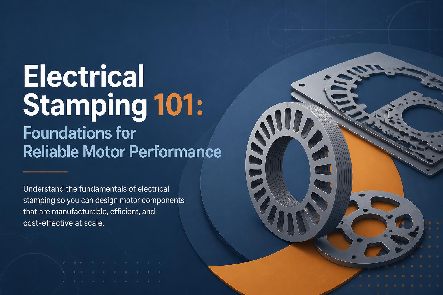
When a motor runs hotter than expected, vibrates, or fails early, the root cause is often hidden inside the steel: poorly designed or poorly manufactured electrical stampings. For OEMs, that means warranty claims, noise complaints, and efficiency targets missed by a few painful percentage points.
This guide explains electrical stamping from an OEM and design engineer’s point of view: what actually happens in the press shop, how design choices affect manufacturability and losses, and what to look for in a stamping partner so you get consistent rotor and stator laminations at scale.
If you want to go deeper into specific topics later, you can explore our resources on designing rotor and stator laminations, progressive die stamping for motor components, and magnetic core manufacturing. This article ties those threads together at the “Electrical Stamping 101” level.
What is electrical stamping?
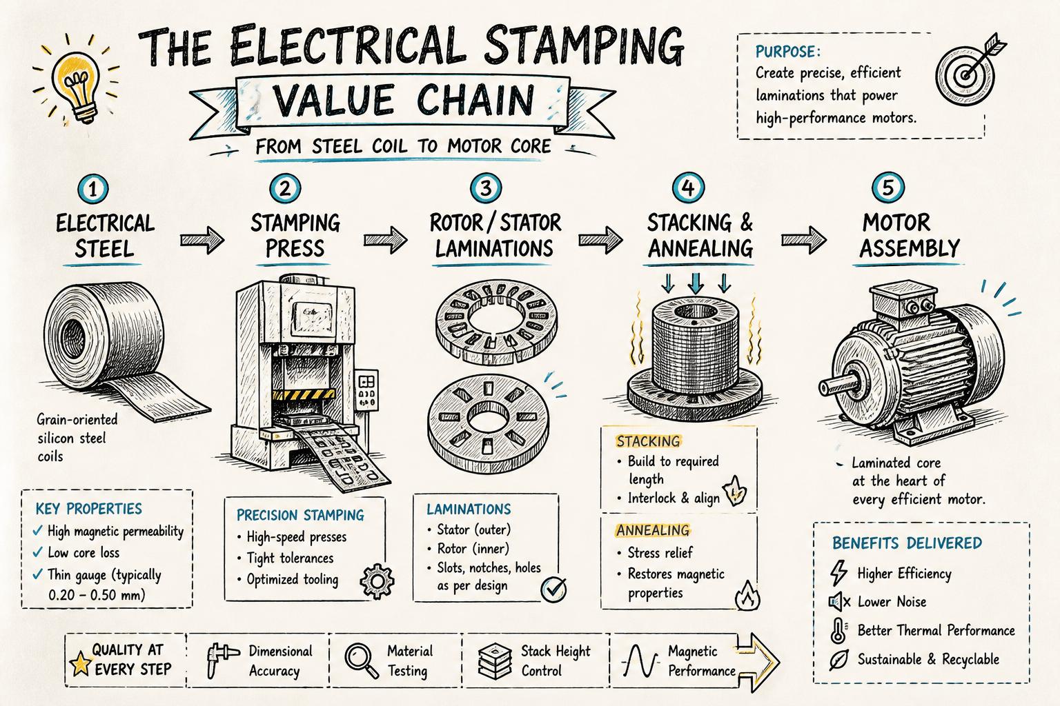
Electrical stamping is the process of punching thin electrical steel sheets into precise shapes used in motors, transformers, and other electromagnetic devices. In motors, these shapes are primarily:
Stator laminations – stationary outer core with slots for windings
Rotor laminations – rotating inner core, often for die-cast rotors
Instead of using a solid block of steel, manufacturers build the magnetic core from stacks of thin laminations. This reduces eddy current losses and allows better control over magnetic performance. But that only works if each lamination is:
Cut to tight stamping tolerances
Free from excessive burrs and distortion
Made from the specified electrical steel grade and coating
Electrical stamping is therefore both a mechanical and a magnetic process. Tooling, press parameters, and material handling all influence the final core loss and efficiency of the motor.
A few microns of extra burr or a fraction of a millimetre of slot misalignment may look harmless on a single lamination. Across a 100–300 piece stack, those errors compound into real performance problems.
1. Core losses and efficiency
Core losses in motors are mainly:
Stamping affects both:
Mechanical damage in the shear zone (around the punched edge) locally increases hysteresis loss.
Burrs and smeared insulation coating can create electrical bridges between laminations, increasing eddy currents.
According to widely cited data on electrical steels from manufacturers like AK Steel / Cleveland-Cliffs, poor punching practices can increase core loss by several percent compared to optimized stamping and annealing. For high-efficiency motors, that is the difference between meeting and missing regulatory targets.
2. Noise, vibration, and harshness (NVH)
Uneven tooth geometry, misaligned slots, or eccentric stacks lead to:
End users experience this as “noisy motors.” For appliances and HVAC equipment, NVH is often as important as raw efficiency.
3. Thermal behaviour and lifetime
Higher core loss means more heat generated in the stator and rotor. This raises winding temperature, accelerates insulation aging, and shortens bearing life. A stamping issue that looks minor on paper can translate to years of lost lifetime in the field.
4. Assembly fit and downstream scrap
Inconsistent lamination dimensions or excessive burrs cause:
High press-fit forces or loose fits in housings and shafts
Stack height variation that breaks assembly jigs
Extra deburring and rework at the motor plant
For high-volume OEMs, a small increase in lamination scrap or assembly time can wipe out the savings from cheaper stampings.
Key elements of the electrical stamping process
Whether you are buying laminations or designing them, it helps to understand the main stages of the motor stamping process.
1. Material selection: electrical steel and insulation coating
Electrical stampings are typically made from non-oriented electrical steel (NOES) for rotating machines and grain-oriented electrical steel (GOES) for transformers and some special machines.
For motors, key parameters of electrical steel are:
Thickness (e.g., 0.35 mm, 0.5 mm) – thinner laminations reduce eddy current loss but increase stamping complexity and cost.
Core loss values at specified flux density and frequency (e.g., W/kg at 1.5 T, 50 Hz).
Permeability – affects magnetizing current and torque capability.
Insulation coating class – determines interlaminar resistance, punchability, and compatibility with annealing and bonding.
Standards like IEC 60404 for magnetic materials define how these properties are measured and specified.
2. Coil handling and blanking
Electrical steel usually arrives in coils. A typical line includes:
Decoiler and straightener – feeds flat material into the press at controlled tension.
Feeder – advances the strip to match the die pitch.
Lubrication system – reduces tool wear and burr height.
For simpler parts, the process may include a blanking step (cutting discs) followed by secondary operations. For high-volume motor components, progressive die stamping combines multiple operations in a single tool and stroke.
To understand when progressive tooling makes economic sense, see our guide on progressive die stamping for motor components.
The heart of electrical stamping is the die set. For motor laminations, typical die functions include:
Outer diameter (OD) and inner diameter (ID) punching
Slot punching – straight or skewed, open or semi-closed
Notches and keyways
Indexing features for in-tool stacking or interlocking
High-quality rotor and stator tools are designed to control:
Clearance between punch and die to manage burrs vs. tool wear
Strip layout to minimize material waste
Thermal expansion and deflection at production speeds
Our detailed article on designing rotor and stator laminations explains how tooth shape, slot geometry, and bridges should be chosen with both electromagnetic and tooling constraints in mind.
4. Press operation: tonnage, speed, and control
Presses for electrical stamping range from medium to high tonnage and must deliver:
Sufficient press force for the total cutting perimeter and material thickness
Stable shut height and parallelism for consistent clearances
Controlled stroke rate to balance throughput, burr height, and tool life
Modern press lines often include monitoring for force signatures, misfeeds, and tool overloads to prevent damage and maintain quality.
5. Stacking, bonding, and annealing
After stamping, laminations must be assembled into cores. Common stacking methods include:
Loose stacking followed by clamping or welding
Interlocking features formed in the die to mechanically lock laminations
Bonded stacks using adhesive or special coatings
For many motor cores, especially higher-efficiency designs, an annealing process is used to relieve punching stresses and restore magnetic properties. Our overview of magnetic core manufacturing covers how annealing, stacking, and testing come together.
Critical stamping tolerances for motor laminations
From a design and sourcing perspective, understanding which dimensions truly matter helps you write better drawings and supplier specifications.
1. Outer and inner diameters (OD / ID)
OD and ID control:
Fit into the housing (stator OD)
Fit onto the shaft or rotor can (rotor ID)
Airgap – the radial clearance between stator and rotor
Too tight, and you get assembly issues or distortion during press-fitting. Too loose, and you risk eccentricity, increased noise, and reduced efficiency.
2. Slot geometry and position
Slot dimensions directly affect:
Fill factor – how much copper you can pack into the slot
Leakage reactance and torque characteristics
Mechanical strength of teeth and bridges
Important tolerances include:
Angular errors can cause cogging torque and uneven airgap fields, especially in permanent magnet and BLDC designs.
3. Stack height and flatness
The total stack height must match the magnetic and mechanical design. Variation here affects:
Axial flux path length and torque capability
Fit into housings and end shields
Rotor balance and bearing loads
Flatness of stack faces influences how well end plates, fans, and bearings seat, and can contribute to axial runout.
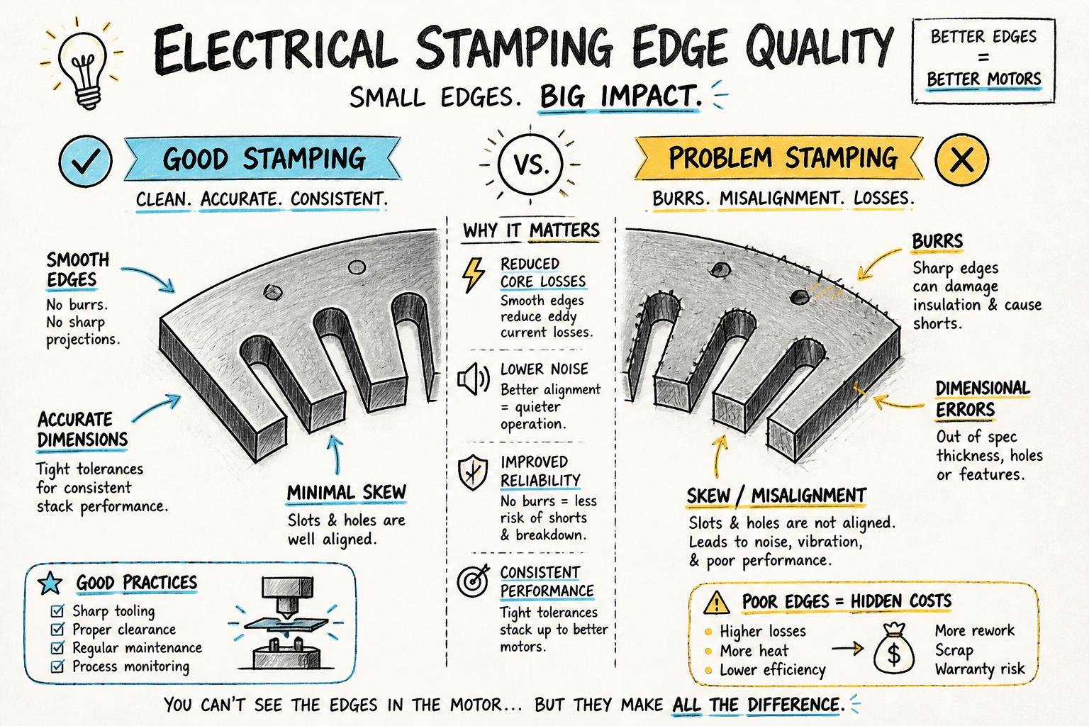
4. Burr height and edge quality
Burrs are a by-product of shearing. For electrical stampings, excessive burrs:
Damage insulation coating and reduce interlaminar resistance
Increase local flux density at sharp edges
Interfere with stacking and cause tilt
Good practice is to define a maximum burr height and, where necessary, specify whether burrs must be oriented in a specific direction (e.g., away from the airgap).
5. Lamination alignment and skew
Many motor designs use skewed slots to reduce cogging torque and noise. This can be achieved by:
Stamping skew directly in the lamination (complex tool)
Stepped skew during stacking (simpler tool, controlled assembly)
Poor control of skew angle or lamination alignment leads to inconsistent performance and higher scrap during rotor and stator assembly.
Designing for manufacturable, efficient electrical stampings
Design engineers often optimize electromagnetic performance in simulation, then hand over drawings that are difficult or expensive to stamp. A better approach is to iterate with your stamping manufacturer early.
Features that drive up tool complexity and cost include:
Very thin bridges and teeth
Extremely tight corner radii
Multiple slot shapes in one lamination
Non-repetitive features that break progressive strip layouts
Ask your supplier to review your lamination design for strip layout efficiency and critical vs. non-critical tolerances. Our guide on lamination stamping design outlines specific design adjustments that often reduce cost without hurting performance.
2. Choose appropriate material thickness and grade
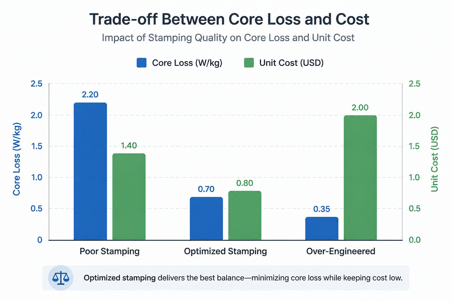
Thinner steel and premium grades lower losses but raise material and tooling cost. The optimal point depends on:
Motor duty cycle and efficiency targets
Energy cost over lifetime vs. product price sensitivity
Regulatory requirements (e.g., IEC efficiency classes)
A practical way to decide is to compare total cost of ownership for end users. The U.S. Department of Energy’s resources on energy-efficient electric motors provide useful frameworks for such calculations.
3. Define tolerances where they matter (and relax where they don’t)
Over-tolerancing is a common reason for high stamping cost. Work with your manufacturer to:
Identify dimensions that directly affect the airgap, slot fill, and fits – keep these tight.
Relax cosmetic or non-functional dimensions to reduce tool maintenance and inspection burden.
Use geometric tolerancing (e.g., concentricity, runout) where it better reflects functional requirements than simple linear tolerances.
4. Plan for stacking and downstream processes
Decisions made at the lamination design stage affect:
Whether stacks will be loose, interlocked, or bonded
How rotors will be die-cast and what venting or riser features are needed
How stators will be wound and impregnated
At ASA Industries, for example, we coordinate electrical stamping, die-cast rotor manufacturing, and annealing so that lamination design, casting tooling, and heat treatment all align with the motor’s performance targets.
One of the biggest cost and capability decisions in electrical stamping is whether to use progressive dies or simpler single- or compound tools.
Progressive die stamping
In progressive die stamping, a strip of electrical steel moves through multiple stations inside one die. Each press stroke performs several operations (e.g., slot punching, OD/ID cutting, interlocking) until a finished lamination exits.
Benefits include:
High production rates and lower cost per piece at volume
Excellent repeatability and alignment between features
Possibility of in-tool stacking or interlocking
Trade-offs:
Our article on progressive die stamping for motor components explains when the economics favour this route.
For lower volumes, frequent design changes, or very large laminations, manufacturers may use:
Single-operation tools – one feature per stroke
Compound tools – multiple features in one station (e.g., OD and ID together)
Stage tools – a series of simpler tools in sequence
These options lower tooling cost and risk but usually increase part cost and may require more handling between operations.
Quality control and testing in electrical stamping
To ensure that stamped laminations translate into reliable motors, a robust quality system is essential. When evaluating a stamping manufacturer in India or elsewhere, ask how they control the following.
1. Incoming material inspection
Checks typically include:
Verification of steel grade and coating against mill certificates
Thickness and flatness measurement
Visual inspection for rust, damage, or coil edge defects
2. In-process dimensional and burr control
During production, key controls include:
First-piece and periodic dimensional checks (OD, ID, slots, stack height)
Burr height measurement and tool wear monitoring
SPC (statistical process control) on critical dimensions
3. Magnetic and electrical testing
For motor cores, advanced manufacturers perform:
These tests provide a direct link between stamping conditions and motor performance, beyond simple dimensional checks. Our article on magnetic core manufacturing describes how these tests fit into the broader core production process.
4. Final inspection and traceability
For OEM programs, it is good practice to require:
Documented control plans and inspection records
Lot traceability back to steel coils and process parameters
Clear non-conformance handling and corrective action procedures
How to evaluate a stamping manufacturer for electrical motors
Selecting the right partner is as important as getting the design right. We have a full checklist in our guide on how to choose a stamping manufacturer in India for motor components; below is a summary tailored to electrical stamping.
1. Technical capabilities
Key questions to ask:
What press tonnage range and stroke speeds can you handle?
Do you design and maintain tooling in-house?
What experience do you have with my motor type (single-phase induction, BLDC, shaded pole, universal)?
Can you also supply die-cast rotors, annealing, and testing so I have a single accountable supplier?
2. Quality systems and certifications
Look for:
ISO-certified quality management (e.g., ISO 9001 or IATF 16949 for automotive)
Documented APQP / PPAP processes for new part introduction
Use of SPC, capability studies, and FMEAs on critical characteristics
3. Experience with electrical motor laminations
Ask for examples of:
Programs where they improved core loss or NVH through stamping optimization
Types of motors and power ranges they regularly supply
Any co-development projects with OEMs for high-efficiency or specialty motors
4. Supply chain reliability
For OEMs, the best stamping supplier is often the one you never have to think about because delivery and quality are stable. Evaluate:
On-time delivery history and buffer stock policies
Backup presses and tooling maintenance practices
Ability to ramp up for new model launches or seasonal demand
Common pitfalls in electrical stamping (and how to avoid them)
1. Treating laminations as a pure commodity
Lowest piece price is tempting, but ignoring tooling, process control, and magnetic performance often leads to:
Hidden energy losses for end users
Higher field failure rates and warranty costs
Last-minute firefighting during motor certification
Consider total cost, including energy and warranty, not just stamping price.
2. Late involvement of the stamping partner
Bringing the stamping manufacturer in only after the motor design is frozen limits optimization options. Instead:
Share preliminary lamination CAD and performance targets early.
Ask for DFM feedback on slot shapes, bridges, and tolerances.
Plan prototype tools or soft tooling before committing to full progressive dies.
3. Ignoring annealing and testing
Skipping annealing or relying solely on mill certificates for magnetic properties can be risky, especially for high-efficiency designs. Work with suppliers who can:
Provide in-house annealing with controlled atmospheres
Perform core loss testing on stamped and annealed samples
Support motor-level validation with surge and performance tests
How ASA Industries supports reliable electrical stamping for motors
ASA Industries has been manufacturing electrical motor components since 1985, with a focus on:
Electrical stamping for rotor and stator laminations across single-phase induction, BLDC, universal, and shaded pole motors
Progressive die stamping for high-volume, multi-geometry components
Die-cast rotor manufacturing with surge testing
Magnetic core manufacturing and annealing with Epstein testing
Sheet metal components for electrical appliances and industrial equipment
With high-tonnage presses, in-house precision tooling, CNC machining, and ISO-certified quality systems, we support OEMs from early design input through to stable series production.
Next steps: turning electrical stamping theory into reliable motors
If you are designing or sourcing motor laminations, use this article as a checklist:
Clarify your performance targets (efficiency, NVH, lifetime).
Choose electrical steel and insulation coatings aligned with those targets.
Design laminations with manufacturability in mind, especially slots, bridges, and tolerances.
Select a stamping manufacturer with the tooling, process control, and testing capabilities to back up your design.
To discuss a specific motor program or review your lamination drawings for manufacturability, you can reach out to ASA Industries for a technical consultation. Our team can help translate your performance requirements into practical, scalable electrical stamping solutions that hold up in real-world production.