When you are scaling an electric motor program, tooling choices can quietly make or break your business case. Progressive die stamping promises speed, consistency, and lower cost per part — but only if the volumes, part design, and quality requirements justify the higher upfront investment.
This explainer walks through when progressive die stamping makes sense for motor components, how it compares to simpler tools, and how to build a solid ROI case for long‑run OEM programs. We will stay practical and focus on applications like stator and rotor laminations, motor brackets, and other electrical stampings.
If you are still getting familiar with the basics of electrical stamping, you may want to review our overview on electrical stamping fundamentals first, then come back to this deeper dive on tooling strategy.
What is progressive die stamping in the context of motor components?
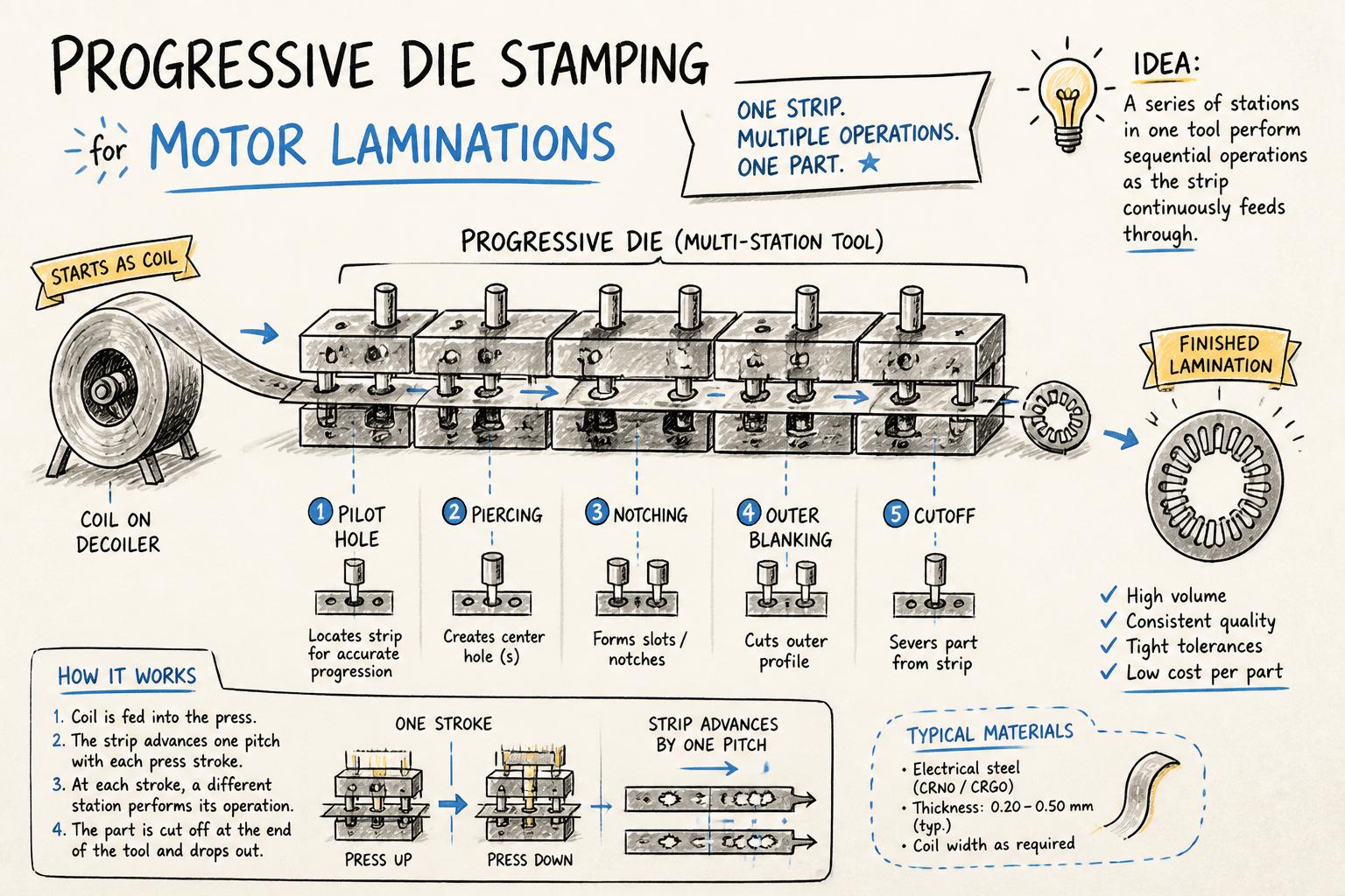
In progressive die stamping, a strip or coil of electrical steel or sheet metal feeds continuously through a multi‑station tool. At each press stroke, the strip indexes forward by a fixed pitch and different operations are performed in sequence — piercing, notching, embossing, forming, and finally blanking the finished part.
For motor components, this often means:
Piercing slots and ventilation holes in stator and rotor laminations
Notching keyways or alignment features for stacks
Coining or embossing identification marks or minor forms
Blanking the final lamination or bracket geometry from the strip
Compared to single‑hit or compound tools, the key difference is that all or most features are produced in one continuous feed stamping process, with the part only leaving the strip at the last station.
Before deciding if progressive tooling is right for your motor program, it helps to compare it with simpler options: single‑hit (or simple) dies and compound dies.
Simple / single‑hit dies
Simple dies perform one primary operation per stroke — for example, blanking a rotor lamination from pre‑slit strip, or punching a pattern of ventilation holes.
Pros: Lowest tooling cost, fastest to develop and modify, flexible for design changes and low volumes.
Cons: Multiple setups and tools needed for a finished part, higher labor content, slower throughput, more handling (and therefore more risk of damage or mix‑ups).
Compound dies
Compound dies perform two or more operations in a single station — typically piercing and blanking in one stroke. They are common for relatively flat motor laminations with moderate feature complexity.
Pros: Fewer setups than simple dies, decent productivity, medium tooling investment.
Cons: Still not as fast or integrated as progressive dies; limited when you need multiple stages of piercing, notching, or forming.
Progressive dies
Progressive dies combine many sequential operations in one tool, using precision pilots and strip layout to maintain registration.
Pros: Highest strokes per minute and parts per hour, excellent repeatability, minimal manual handling, good material utilization, suitable for high‑volume OEM programs.
Cons: Highest tooling cost and longest build time, more complex maintenance, less forgiving of late design changes.
Our in‑depth guide to designing rotor and stator laminations for high‑efficiency motors explains how these tooling choices interact with lamination geometry, burr direction, and stacking strategy.
When progressive die stamping makes sense for motor components
Progressive tooling is not automatically the right answer just because you want to "automate" stamping. It makes sense when a specific combination of factors is present.
1. Annual volumes are high and stable
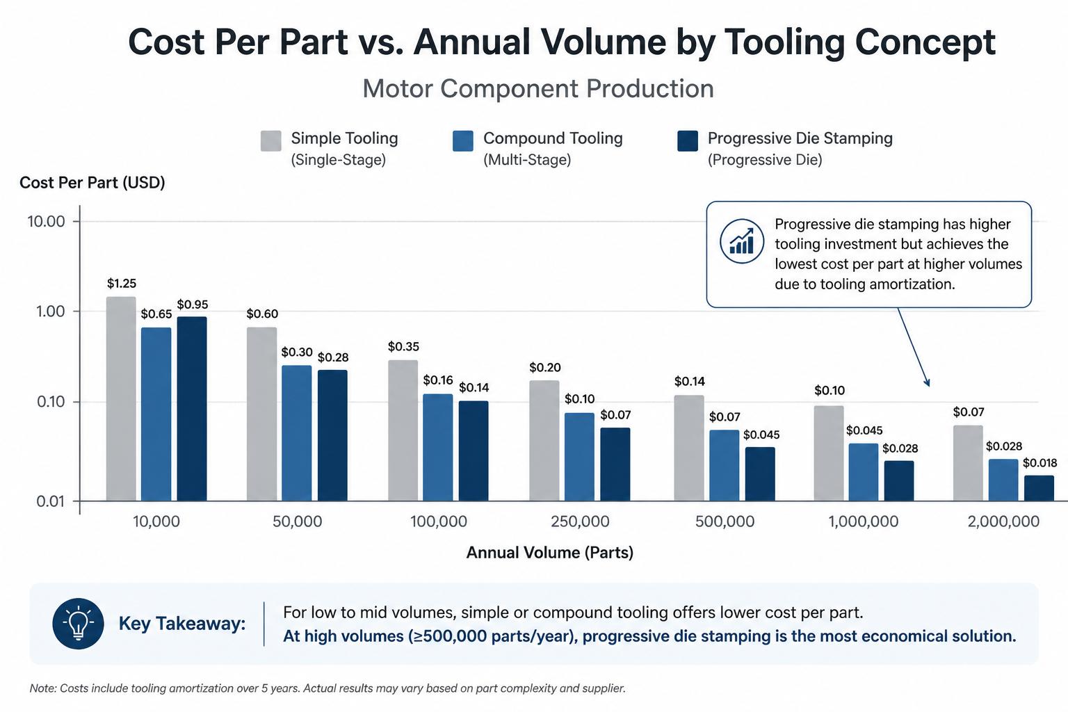
The single biggest driver is volume. Progressive dies shine when you can amortize the tooling over many parts.
For small to medium motor laminations or brackets, progressive dies often become economical above 200,000–300,000 parts per year per variant.
For very small parts (e.g., BLDC rotor segments or small appliance laminations), the break‑even can be lower because cycle times are extremely high.
For large, thick laminations or low‑volume industrial motors, simple or compound dies may remain more sensible.
Your stamping partner should model tooling amortization across the expected program life (often 5–7 years for appliance motors) to show how cost per part declines as volume increases.
2. Part geometry has multiple features that can be integrated
Progressive die stamping delivers maximum benefit when you can combine many operations that would otherwise require several tools or passes.
Typical examples in electric motor and appliance components:
Stator laminations with slots, notches, indexing holes, and ventilation patterns
Rotor laminations with skewed slot patterns (handled via strip layout and pilot design)
End shields, brackets, or mounting plates that need piercing, embossing, and forming
Sheet metal components for appliance housings with multiple cutouts and bends (see our guide on sheet metal components for electrical appliances for DFM tips)
If your component is a simple round blank with few features, the productivity gain from progressive tooling may not justify the extra complexity.
3. Tight tolerances and repeatability are critical
Because the strip remains guided through the entire tool, progressive dies offer excellent positional accuracy between features. This is especially valuable when:
Slot pitch and concentricity directly affect motor efficiency and noise
Stack alignment is critical for automated assembly or die casting
Downstream processes (e.g., winding, die‑cast rotor insertion) rely on tight fits
Standards such as ASTM A684 for electrical steel strip and motor efficiency regulations (like IEA guidance on motor system efficiency) are pushing OEMs toward tighter control of magnetic and dimensional performance. Progressive dies help meet these expectations consistently at scale.
4. You want to reduce manual handling and in‑process inventory
With simple tooling, partially processed laminations often move between presses, accumulating work‑in‑process inventory and handling risk. Progressive dies keep the part attached to the strip until the final station, so:
There is less chance of damage, mixing, or contamination.
Inspection can focus on strip samples rather than loose parts at every stage.
Automation (coil feeding, straightening, and stacking) is easier to implement.
For OEMs under pressure to adopt lean manufacturing and reduce floor space, this consolidation of operations can be a significant advantage.
5. Design is mature and unlikely to change frequently
Because progressive dies are more complex and expensive to modify, they are best suited to stable, mature designs. If you expect several design iterations during the first year of production, a staged approach can make sense:
Start with simpler tooling during validation and early ramp‑up.
Freeze the design once performance and manufacturability are confirmed.
Invest in progressive tooling for the long‑run, steady‑state production.
This is a common pattern for appliance and HVAC OEMs sourcing single phase induction motor components or BLDC motor laminations.
Once you decide that a progressive die is justified, part and strip design must be aligned with how the tool will run. Poor early decisions can lock in unnecessary cost or limit productivity.
Strip layout and material utilization
Progressive tools require a carefully engineered strip layout that balances material yield with tool stability and feature accuracy.
For round laminations, you may use interlocking or nested layouts to reduce scrap while maintaining carrier strength.
For irregular brackets or housings, you may accept slightly lower yield in exchange for robust strip guiding and simpler tooling.
Web widths, pilot locations, and carrier design must consider both press tonnage and strip stiffness.
Our article on magnetic core manufacturing explains how material choice and lamination thickness interact with stamping strategy and losses.
Station sequencing and feature interactions
In progressive tool design, the order of operations is critical. Typical sequences for motor laminations might be:
Designers must avoid situations where early operations weaken the strip so much that later stations become unstable. They also need to manage burr direction, as it affects stacking, annealing, and sometimes motor performance.
Tonnage, press selection, and speed
A progressive die for electrical motor components must be matched to a press with adequate:
Capacity (tonnage) for peak cutting load plus forming loads
Bed size and shut height for the overall tool footprint
Speed capability (strokes per minute) for the desired output
For example, ASA Industries uses 125–360 Ton high‑tonnage power presses to run progressive dies for a range of motor laminations and sheet metal components. Proper press selection directly influences achievable throughput and tool life.
Quality control and in‑die sensing
Because progressive tools run at high speed, in‑die sensing and robust quality systems are essential. Typical controls include:
Strip feed and end‑of‑stock sensors
Slug detection and misfeed detection
In‑process dimensional checks at defined intervals
For critical motor applications, additional testing such as Epstein testing of annealed stators or surge testing of die‑cast rotors helps ensure that stamping quality translates into magnetic and electrical performance.
How progressive dies impact cost per part
From a purchasing perspective, the key question is: How will progressive tooling change my piece price and total landed cost?
Progressive dies typically cost several times more than simple or compound tools. However, they also reduce:
Cycle time (more parts per hour)
Labor (fewer operators and setups)
Scrap (better material utilization, fewer damaged parts)
A basic ROI model should include:
Tooling investment (including spares and expected major overhauls)
Expected annual volume and program duration
Difference in piece price between simple/compound and progressive tooling
Indirect savings from reduced handling, floor space, and quality incidents
Many OEMs target a tooling payback period of 12–24 months, but acceptable thresholds vary by organization and product line.
Impact on stamping productivity and OEE
Progressive dies can dramatically improve stamping productivity and Overall Equipment Effectiveness (OEE) by:
Reducing changeover time (one tool instead of several)
Enabling higher strokes per minute for continuous runs
Lowering defect rates due to consistent registration and fewer handling steps
Studies in high‑volume metal stamping environments (for example, analyses published by the Society of Manufacturing Engineers) consistently show that integrated tooling and reduced setups are major levers for OEE improvement.
Total cost of ownership for long‑run OEM programs
For long‑run motor programs, piece price is only part of the story. Progressive dies also influence:
Supply risk: Fewer process steps mean fewer potential failure points across your supply chain.
Quality stability: Once the tool is dialed in, dimensional variation stays low over large batches.
Scalability: It is easier to ramp volumes or replicate capacity when the process is standardized around progressive tooling.
When you present a business case internally, including these factors strengthens the argument for investing in progressive dies.
Decision framework: is progressive die stamping right for your part?
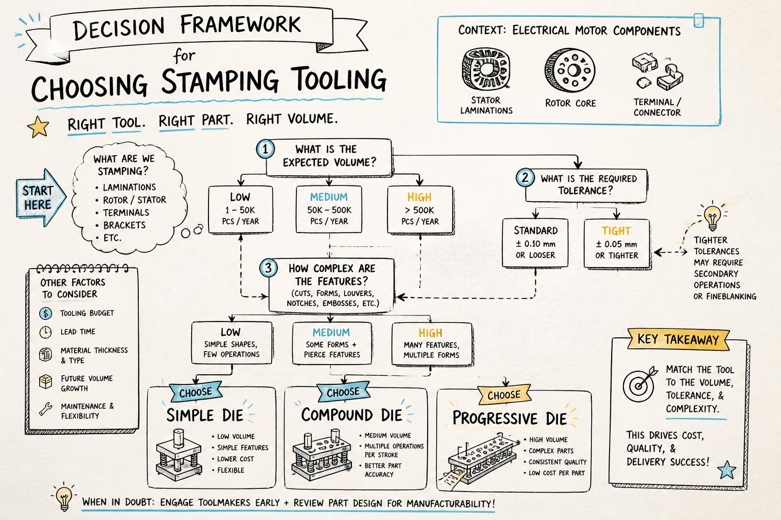
To bring this together, it helps to use a simple decision framework. Consider four main dimensions: volume, geometry, tolerance, and lifecycle.
1. Volume
Prototype < 5,000 pcs/year: Laser cutting or simple dies.
Low volume 5,000–100,000 pcs/year: Simple or compound dies.
Medium volume 100,000–300,000 pcs/year: Evaluate compound vs. progressive; decision depends heavily on geometry and required takt time.
High volume > 300,000 pcs/year: Progressive dies usually favored, especially for multi‑feature parts.
2. Geometry and feature count
Very simple geometry (basic round or rectangular blanks): Simple or compound dies usually adequate.
Moderate complexity (several holes, notches, minor forms): Compound or short progressive dies.
High complexity (many slots, notches, embosses, forms): Progressive dies preferred to consolidate operations.
3. Tolerance and quality requirements
Loose tolerances, manual assembly: Simple dies may be fine.
Moderate tolerances, some automated assembly: Compound or progressive.
Tight tolerances, highly automated stacking or die casting: Progressive dies strongly recommended.
4. Product lifecycle and design maturity
Early development, frequent design changes: Avoid large progressive investments; use flexible tooling.
Mature design, long‑term OEM contract: Progressive dies typically deliver the best total cost of ownership.
What to look for in a progressive die stamping partner
Choosing the right manufacturing partner is as important as choosing the right tooling concept. A capable supplier should offer:
In‑house progressive tool design and maintenance, including experience with electrical steel and motor laminations.
Appropriate press capacity (tonnage, speed, coil handling) for your part family.
Robust quality systems (ISO certification, SPC, incoming and final inspection).
Value‑engineering support to optimize strip layout, material usage, and stamping productivity.
Our guide on how to choose a stamping manufacturer in India for motor components provides a detailed checklist you can use during supplier audits and RFQ evaluations.
How ASA Industries approaches progressive die stamping
ASA Industries specializes in progressive die stamping for electrical motor components, supporting OEMs across appliance, HVAC, automotive, and industrial sectors. Our approach emphasizes:
End‑to‑end tooling support: Design, manufacture, and maintenance of progressive dies for stator and rotor laminations, brackets, and sheet metal components.
Integrated processes: Stamping, annealing, magnetic core assembly, die‑cast rotor production, and CNC machining under one roof.
Quality and testing: ISO‑certified systems, Epstein testing for stamped and annealed stators, and surge testing for die‑cast rotors.
Scalable capacity: High‑tonnage presses (125–360 Ton) and aluminium die casting machines (80–250 Ton) to support long‑run OEM programs.
If you are evaluating progressive die stamping for a new or existing motor program, we can help you compare tooling options, estimate payback, and design components that run reliably at scale.
Next steps
Review your current or planned motor components and classify them by volume, geometry, tolerance, and lifecycle.
Engage with a stamping partner early to co‑develop progressive tool design and strip layouts.
Use a structured cost model to compare simple, compound, and progressive tooling, including tooling amortization and productivity impacts.
Explore related resources on electrical stamping fundamentals and lamination stamping design to strengthen your internal specifications.
When these elements are aligned, progressive die stamping can transform the economics and reliability of your motor component supply — turning a higher upfront tooling cost into a long‑term competitive advantage.