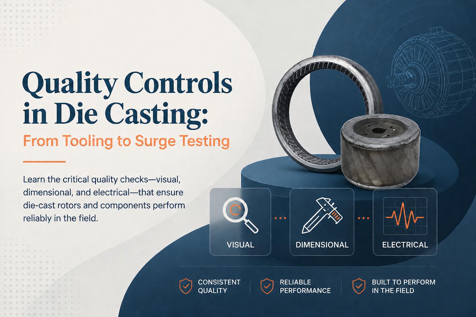
Die casting quality control is where promising motor programs are either secured for years—or quietly derailed by field failures, noise, or inconsistent performance.
If you are sourcing die‑cast rotors or aluminium components for motors, you need more than a supplier who “does inspection.” You need a structured quality system that starts at tooling design and ends at surge testing of finished rotors.
This FAQ walks through that complete chain: from incoming material checks and process capability to porosity control, dimensional and visual inspection, and final electrical validation. For a deeper view of how casting choices affect motor design, see our guide on aluminium die casting for electric motor rotors and housings.
FAQ on Die Casting Quality Control for Rotors and Motor Components
What does a robust die casting quality control system look like end-to-end?
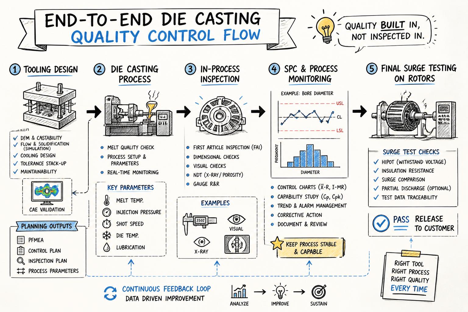
A mature die casting quality control system is not a single inspection step. It is an integrated loop covering:
Tooling and process design (DFM, gate and runner design, venting, cooling)
Incoming material control (alloy certification, melt treatment checks)
In‑process controls (machine parameters, shot monitoring, SPC in die casting)
Product inspection (visual, dimensional, functional)
Final performance tests like surge testing for rotors
Corrective and preventive actions driven by data and feedback from the field
At ASA Industries, this is anchored by an ISO‑certified quality management system with documented procedures, work instructions, and traceability for every batch.
How does tooling design influence die casting quality control?
Most chronic quality issues (porosity, incomplete fill, flash) trace back to tooling design. A quality‑driven program starts with:
DFM reviews with customers to align tolerances, draft, and wall thickness with casting capability
Optimised gating and runner design to ensure balanced fill and avoid cold shuts
Venting strategy to evacuate air and reduce gas porosity
Cooling line layout for consistent solidification and reduced distortion
Tool steel and surface treatment selection to maintain dimensional stability over tool life
If you are in the design phase, it is worth understanding how tooling design for stamping and die casting impacts cost, lead time, and achievable tolerances.
Which standards and certifications matter for die casting quality?
For OEMs, an ISO quality system is the minimum signal that a supplier has structured processes and audits. Commonly referenced standards include:
ISO 9001 for quality management systems
IATF 16949 for automotive applications where applicable
Relevant IEC/IS motor standards for performance and safety requirements
These standards require documented process controls, calibration of gauges, internal audits, and corrective action systems. You can review the core requirements of ISO 9001:2015 for an overview of what a compliant system should include.
What are the critical incoming material controls in die casting?
Even the best die cannot compensate for inconsistent alloy quality. Key incoming controls include:
Supplier certification and lot traceability for aluminium ingots or master alloys
Chemical composition verification against the specified alloy grade (e.g., using spectrometer reports)
Fluxes, release agents, and consumables approved and standardised to avoid contamination
On the shop floor, melt treatment (degassing, fluxing, temperature control) is then monitored to keep hydrogen content and inclusions within limits, which directly affects porosity and surface finish.
How is porosity controlled in die casting?
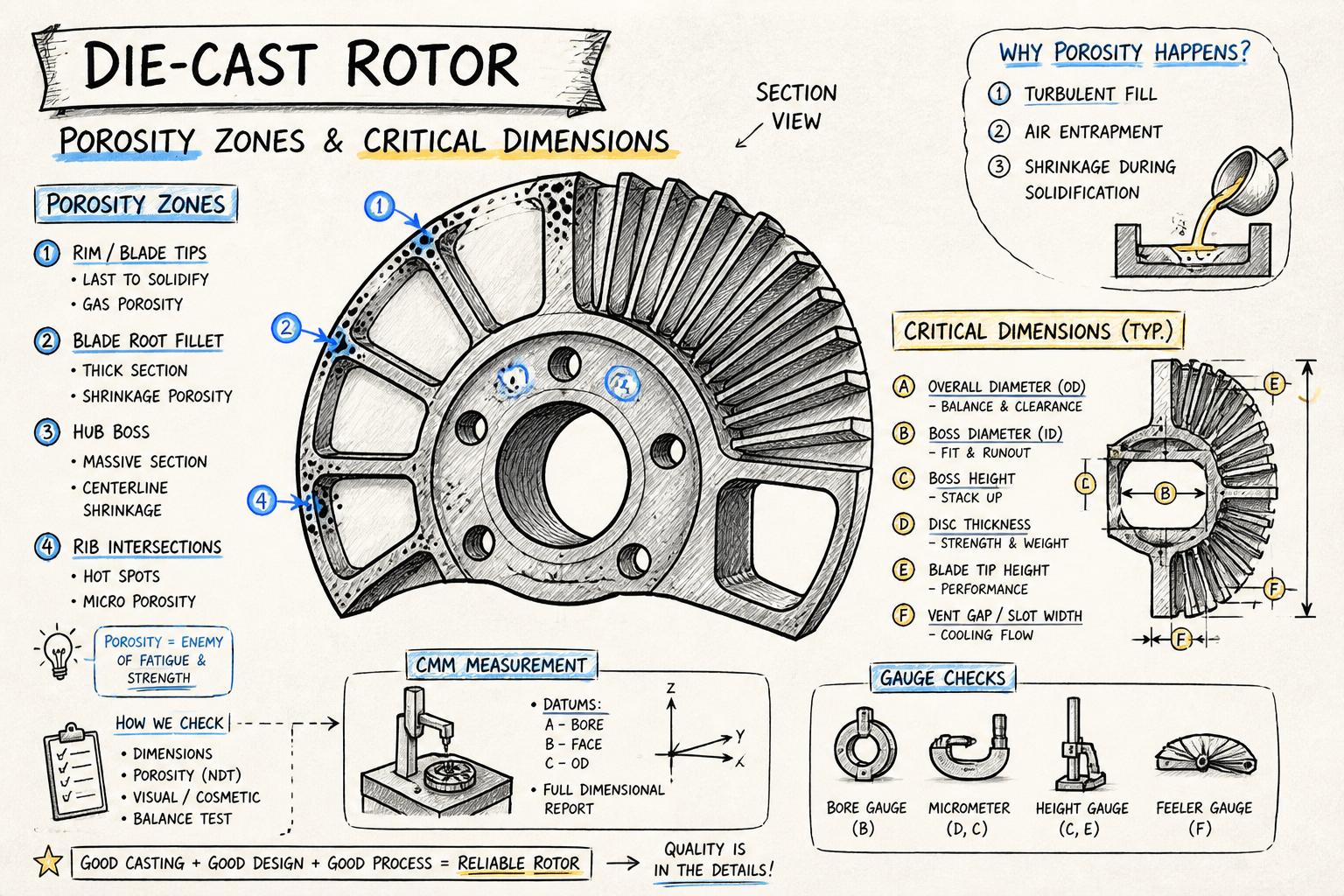
Porosity control is central to die casting quality control, especially for die‑cast rotors where mechanical integrity and electrical performance both matter.
Effective porosity control combines:
Process design: correct gate velocity, shot speed profile, and venting
Melt quality: degassing, filtration, and temperature control
Cycle consistency: stable die temperature and shot‑to‑shot repeatability
Inspection: sectioning, density checks, and where justified, X‑ray sampling
For rotors, porosity near the bar‑to‑end‑ring junctions can severely affect current carrying capacity and surge performance, so these zones receive particular attention during development.
What are the main types of die casting inspection?
A balanced inspection plan typically includes:
Visual inspection: 100% or sampling based on risk, checking for surface defects (cold shuts, misruns, flash, cracks, flow lines, blisters)
Dimensional inspection: using gauges, micrometers, height gauges, and CMM for critical features
Functional inspection: runout, balance, or fit checks with mating parts
Special tests: such as surge testing for rotors or pressure testing for fluid‑handling components
Early in a program, more intensive inspection (including sectioning and higher sampling) is used to validate the process window before shifting to a stable control plan.
How does SPC in die casting improve process capability?
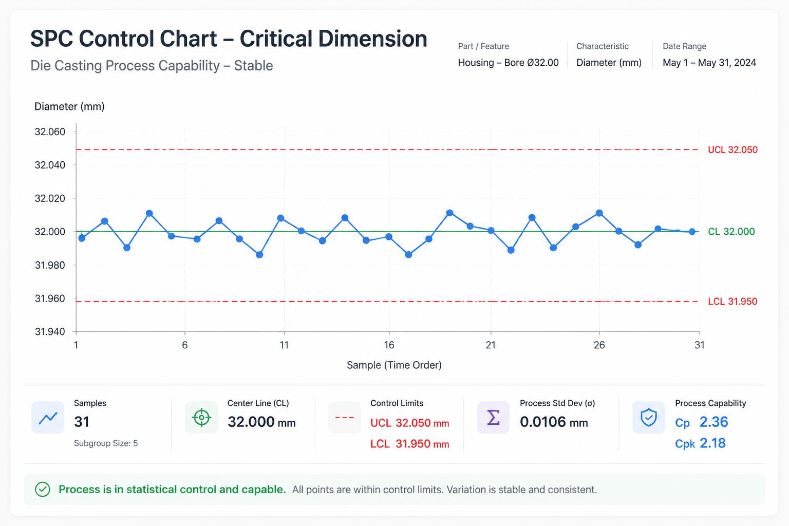
Statistical Process Control (SPC) turns isolated measurements into actionable process intelligence. In die casting, SPC is commonly applied to:
Critical dimensions that affect fit, bearing life, and rotor balance
Weight of casting as a proxy for fill consistency
Key process parameters such as melt temperature or shot speed (where sensors are available)
By plotting these on control charts and calculating indices like Cp and Cpk, the team can see whether the process is capable and stable, not just whether individual parts pass inspection.
Which dimensions on die-cast rotors are usually controlled most tightly?
For die‑cast rotors and motor components, OEMs typically specify tight control on:
Shaft bore diameter and position (for interference or transition fits)
Outer diameter and roundness (influencing air gap and vibration)
Stack height and parallelism for laminated stacks with cast cages
Key dimensions of end rings and bars that influence electrical characteristics
Runout and balance to meet noise and vibration targets
These are typically checked on a defined sampling plan using calibrated gauges and CMMs, with SPC applied to high‑risk features.
How are sampling plans defined for die casting inspection?
Sampling plans balance risk, cost, and process maturity. Common approaches include:
100% inspection for visual defects in early ramp‑up or for safety‑critical parts
Statistical sampling (e.g., using industry‑recognised sampling standards) for stable processes
Dynamic sampling where frequency is increased after a non‑conformance and relaxed after a defined period of stability
An ISO quality system will document these plans in control plans and inspection instructions so that operators and inspectors apply them consistently.
What is surge testing, and why is it critical for die-cast rotors?
Surge testing is an electrical test that applies high‑frequency, high‑voltage pulses to a winding or rotor circuit and compares the response between phases or against a reference. For die‑cast rotors, surge testing helps detect:
Cracked bars or end rings due to casting defects or handling damage
Poor electrical continuity at bar‑to‑ring junctions
Asymmetries that can lead to unbalanced magnetic pull, noise, and efficiency loss
Unlike simple resistance checks, surge testing is sensitive to subtle defects that only show up under electrical stress. This makes it a powerful final quality gate before rotors go into motor assembly.
For OEMs comparing rotor technologies, our article on die‑cast rotor vs fabricated rotor explains how such quality controls influence efficiency and lifecycle cost.
How does surge testing fit into the overall quality control flow?
In a typical rotor production line, surge testing is integrated near the end of the process, after casting, machining (if any), and basic dimensional checks. The flow often looks like:
Die casting with in‑process parameter control
Trimming, deburring, and shot blasting as required
Dimensional and visual inspection per control plan
Balancing or additional machining operations
Surge testing of each rotor or a defined sample, depending on risk level
Final inspection and packing with batch traceability
Integrating surge testing with SPC data on dimensions gives a more complete picture of process capability and product reliability.
What are the most common die casting defects and their root causes?
Typical defects seen in die casting include:
Porosity (gas or shrinkage) – due to poor venting, high gas content, or improper solidification
Cold shuts and misruns – from low melt temperature, slow fill, or poor gate design
Flash – from excessive metal pressure, die wear, or poor clamping
Hot tears and cracks – from constrained solidification or poor die design
Dimensional out‑of‑tolerance – from die wear, thermal distortion, or unstable process settings
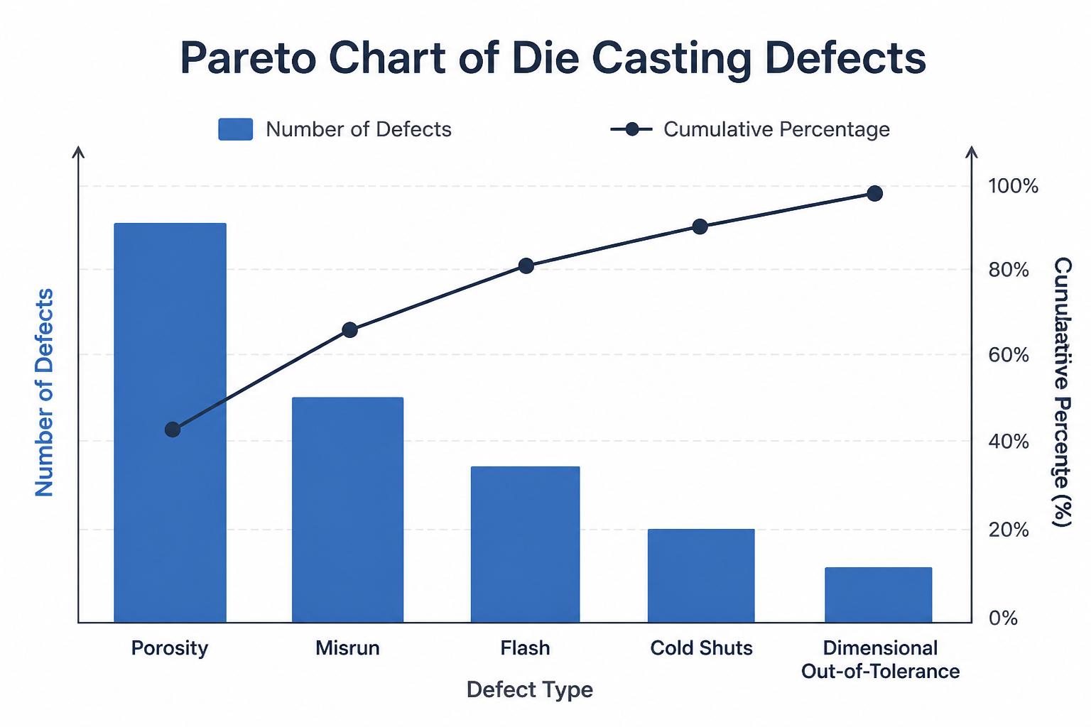
A Pareto analysis of defect types helps focus improvement efforts on the few issues causing most of the rejections.
How do you ensure long-term consistency, not just initial PPAP approval?
Passing initial samples is only the starting point. Long‑term consistency requires:
Documented process windows for critical machine and die parameters
Preventive maintenance on dies and machines to control wear
Ongoing SPC and periodic capability studies on key dimensions
Layered process audits to ensure operators follow work instructions
Feedback loops from motor testing (noise, efficiency, failure analysis) back into casting process improvements
Suppliers with integrated capabilities—stamping, die casting, machining, and testing—can often close these loops faster. Learn how this works in practice in our article on integrating stamping, die casting, and machining in your motor component supply chain.
What should OEMs look for when auditing a die casting supplier?
Beyond certificates, an on‑site audit should verify:
Process control: parameter sheets at machines, real‑time monitoring where applicable
Tooling management: in‑house toolroom, preventive maintenance logs, spare inserts
Inspection capability: calibrated gauges, CMM, documented work instructions
SPC and data usage: visible control charts, reaction plans for out‑of‑control points
Final testing: surge testing or other functional tests relevant to your application
Cleanliness and material handling: segregation of OK/NG parts, labelled bins, traceability
Resources such as the North American Die Casting Association (NADCA) provide additional best‑practice guidelines you can reference in your audit checklists.
How does ASA Industries approach die casting quality control for motor OEMs?
For motor and appliance OEMs, ASA Industries combines:
Aluminium die casting with 80–250 Ton machines and dedicated tooling for rotors and housings
In‑house tooling design, manufacture, and maintenance for consistent quality over tool life
ISO‑certified quality management with documented incoming, in‑process, and final inspection
Advanced quality control including SPC, CMM measurement, Epstein testing for laminations, and surge testing for die‑cast rotors
Integrated stamping and machining so that rotor performance can be validated in the context of the complete motor stack
If you are evaluating die casting suppliers for new or existing motor programs, a conversation focused on process capability, porosity control, and surge testing will reveal quickly whether a partner can support your long‑term quality and cost targets.