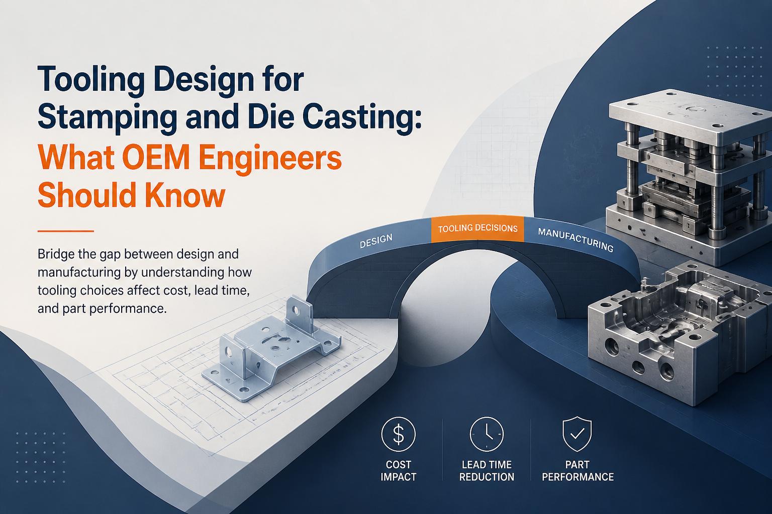
Most OEM engineers feel the impact of tooling only when it is too late: launch delays, unexpected rework, or a part that never quite hits its cost and quality targets. Yet precision tooling design is where many of these outcomes are locked in months earlier.
This explainer will help you see stamping and die casting tools the way your manufacturing and tooling partners do. You will learn how design choices affect part quality, tool life, lead time, and total landed cost—so you can specify smarter, manufacturable parts from day one.
We will focus on progressive stamping dies and aluminium die casting tools for electric motor and appliance components, and how to collaborate with suppliers like ASA Industries to balance performance, cost, and schedule.
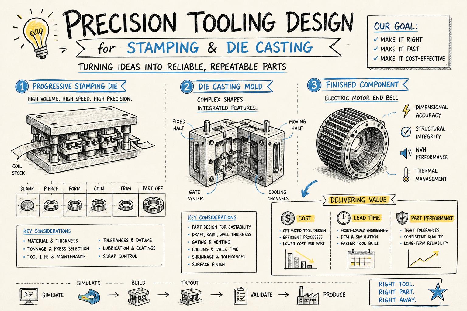
For high-volume stamped laminations, sheet metal parts, and die-cast rotors, tooling is not just a cost line item—it is a strategic lever. Studies in manufacturing engineering consistently show that 70–80% of product cost is committed during design, long before the first tool is cut.1
In stamping and die casting, tooling design directly influences:
Part performance – dimensional accuracy, magnetic properties for laminations, rotor balance, and mechanical strength
Process capability – achievable tolerances, Cp/Cpk, and how often you will fight variation on the line
Tool life and uptime – how often tools need maintenance, regrinding, or unscheduled repair
Scrap and rework – strip layout, gating, and cooling all drive yield and defect rates
Lead time and change flexibility – how quickly you can move from prototype to SOP and respond to design tweaks
If your program relies on lamination stamping, die-cast rotors, or precision sheet metal components, your tooling strategy is as important as your BOM.
For a deeper dive into how tooling choices show up in finished motor components, see our guide on aluminium die casting for electric motor rotors and housings.
Stamping vs die casting: different processes, same design mindset
Progressive stamping and aluminium die casting behave very differently on the shop floor, but OEM engineers should approach their tooling with a similar mindset: design for stable, repeatable production—not just nominal geometry.
Progressive dies are ideal for high-volume electrical stampings and sheet metal parts. A strip of coil material advances through multiple stations, each performing an operation (piercing, forming, blanking) until a finished part exits every press stroke.
Key implications for tooling design:
Strip layout determines material utilization, grain direction, and how stresses flow during forming.
Guiding and piloting control positional accuracy between stations, critical for tight-tolerance laminations.
Clearances, radii, and forming steps dictate burr height, edge quality, and risk of cracking.
ASA Industries uses high-tonnage power presses and in-house tool design to optimize progressive die tooling for rotor and stator laminations, magnetic cores, and appliance stampings.
In aluminium die casting, molten metal is injected under high pressure into a steel mold (die). After solidification, the part is ejected, trimmed, and often machined. For motor rotors and housings, die design governs fill quality, porosity, and dimensional stability.
Key implications for tooling design:
Runner and gate design controls flow, air entrapment, and how well thin sections fill.
Cooling line layout affects cycle time, distortion, and internal stresses.
Ejection and venting influence surface finish, flash, and risk of cracks during ejection.
To understand how die design interacts with downstream validation, including surge testing, review our article on die casting quality controls from tooling to surge testing.
Regardless of process, robust tooling rests on a few core principles OEM engineers should keep in mind when releasing drawings or RFQs.
Most DFM discussions focus on the part: avoid sharp corners, relax tolerances, consolidate features. For stamping and die casting, you also need DFM for tooling—how practical it is to build, maintain, and adjust the tool.
When reviewing designs with your supplier, discuss:
Feature accessibility in the tool – Can critical punches, inserts, or cores be replaced without dismantling half the tool?
Standardization – Are you using standard die sets, guide posts, and components where possible to cut cost and lead time?
Adjustment mechanisms – Are there provisions for shimming, adjusting clearances, or fine-tuning strip progression?
Sensor integration – Can misfeeds, low pressure, or incomplete fill be detected before damage occurs?
A small design change (for example, moving a critical dimension away from a parting line or adding a relief radius) can make the difference between a simple, maintainable tool and a fragile one that constantly needs attention.
Tighter tolerances and sharper corners usually mean more complex, fragile tooling. Precision tooling design is about achieving the functional requirements with the simplest, most robust tool possible.
Ask your supplier to show:
Where tolerances are functionally critical (e.g., air gap in a stator-rotor pair, stack height, bearing fits)
Where tolerances can be widened without affecting motor performance or assembly
Which edges or features drive punch wear and how small design changes could extend tool life
For die-cast rotors, for example, allowing slightly more stock for post-casting machining can dramatically improve die life and reduce scrap, while still meeting final rotor runout and balance requirements. Our comparison of die-cast rotors vs fabricated rotors explains how these trade-offs affect efficiency and lifecycle cost.
3. Specify material and heat treatment with the process in mind
Tool steels, coatings, and heat treatments should match contact conditions and expected volumes.
Stamping tools – For electrical steel laminations, punches see high cyclic loads and abrasive wear. Tool steels like D2, powdered metals, or coated inserts may be justified for long runs and tight tolerances.
Die casting tools – Hot-work tool steels (e.g., H13) and controlled heat treatment are critical to resist thermal fatigue, erosion, and soldering.
As an OEM engineer, you do not need to specify the exact steel grade, but you should challenge overly cheap or overly exotic material choices that do not match your volume and quality needs.
4. Plan for tool maintenance from day one
Tools are living assets, not one-time purchases. A well-thought-out maintenance plan is part of precision tooling design, not an afterthought.
When you review a tooling proposal, ask about:
Preventive maintenance intervals – How often will punches be reground, inserts replaced, or dies polished?
Critical spare parts – Which inserts, punches, or cores will be kept in stock to minimize downtime?
Measurement and tracking – How will tool wear be monitored (e.g., SPC on key dimensions, visual inspection criteria)?
Ownership and storage – Who owns the tool, where is it stored, and how is it protected between runs?
Suppliers with in-house toolrooms, like ASA Industries, can often respond faster to unexpected issues, but only if the tool was designed with maintainability in mind.
For high-volume laminations and sheet metal components, progressive dies are often the most economical choice. Understanding their structure helps you write better drawings and RFQs.
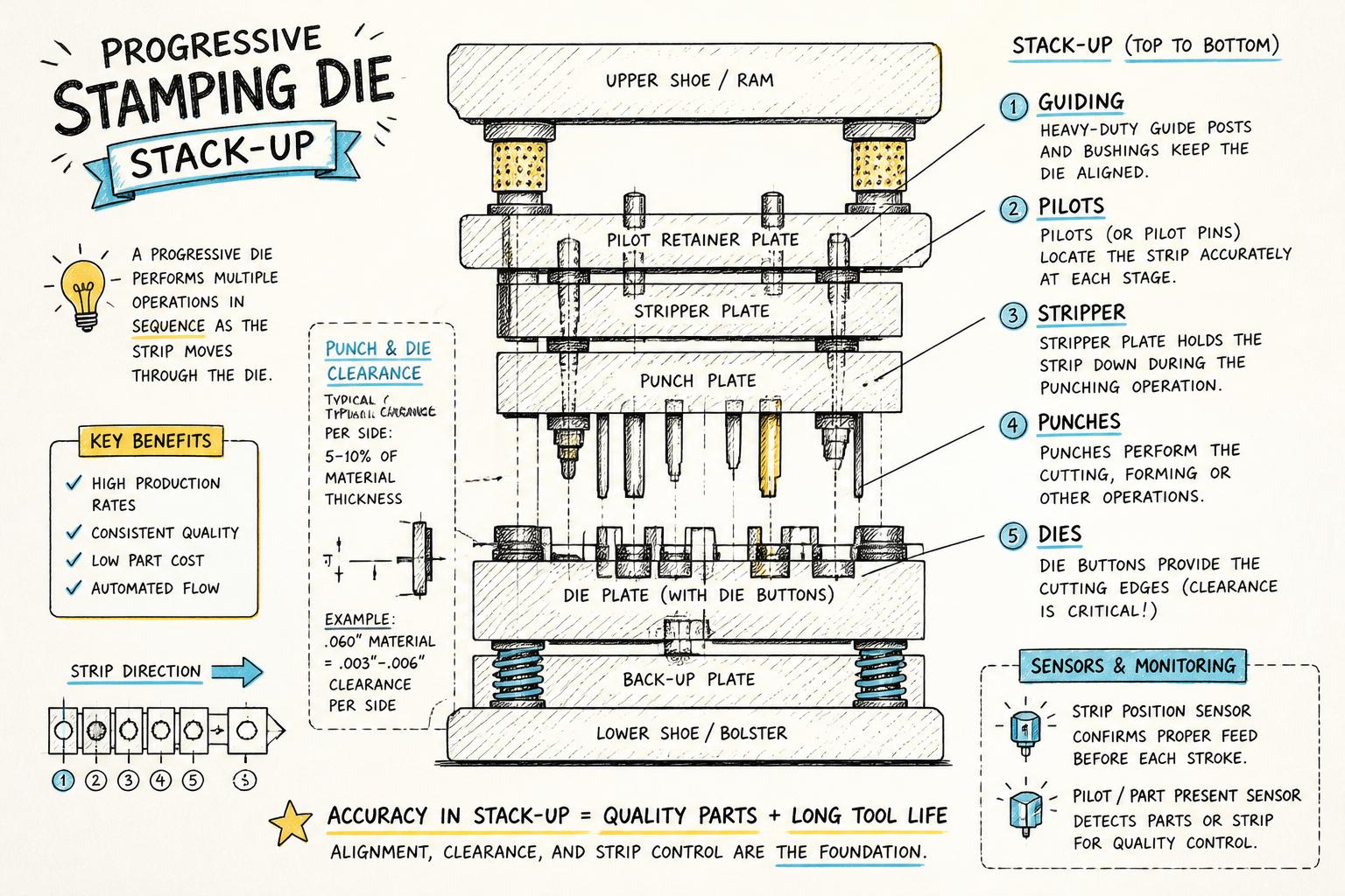
Key elements of a progressive die
Typical components include:
Die set and guiding – Top and bottom plates with guide posts/bushings to ensure alignment.
Stripper and pressure pads – Hold material flat and strip it off punches during retraction.
Punches and dies – Cutting and forming elements; clearances and radii here define edge quality.
Pilots and feed system – Ensure accurate strip progression and station-to-station repeatability.
Stops and lifters – Manage strip height and prevent misfeeds.
Sensors – Detect misfeeds, part-out, or strip break to protect the tool and press.
What you control as an OEM designer
Even if you never touch a die design, your part drawing drives many tooling decisions. To support robust progressive dies:
Avoid unnecessary tight tolerances on non-functional edges; use ISO tolerance classes and GD&T thoughtfully.
Group critical features (e.g., holes and slots that locate the lamination) so they can be produced in the same station where possible.
Respect material limits – minimum web widths, hole-to-edge distances, and bend radii recommended by standards like ASM International or your steel supplier.
Consider grain direction for electrical steel laminations to preserve magnetic performance.
For motor laminations, minor changes in slot geometry or bridge dimensions can have significant effects on both magnetic performance and tool life. Work with a stamping specialist early to co-optimise electromagnetic design and manufacturability.
Die casting tools are more capital-intensive than stamping dies, but they can deliver complex shapes and integrated features that would be impossible or costly to machine from solid.
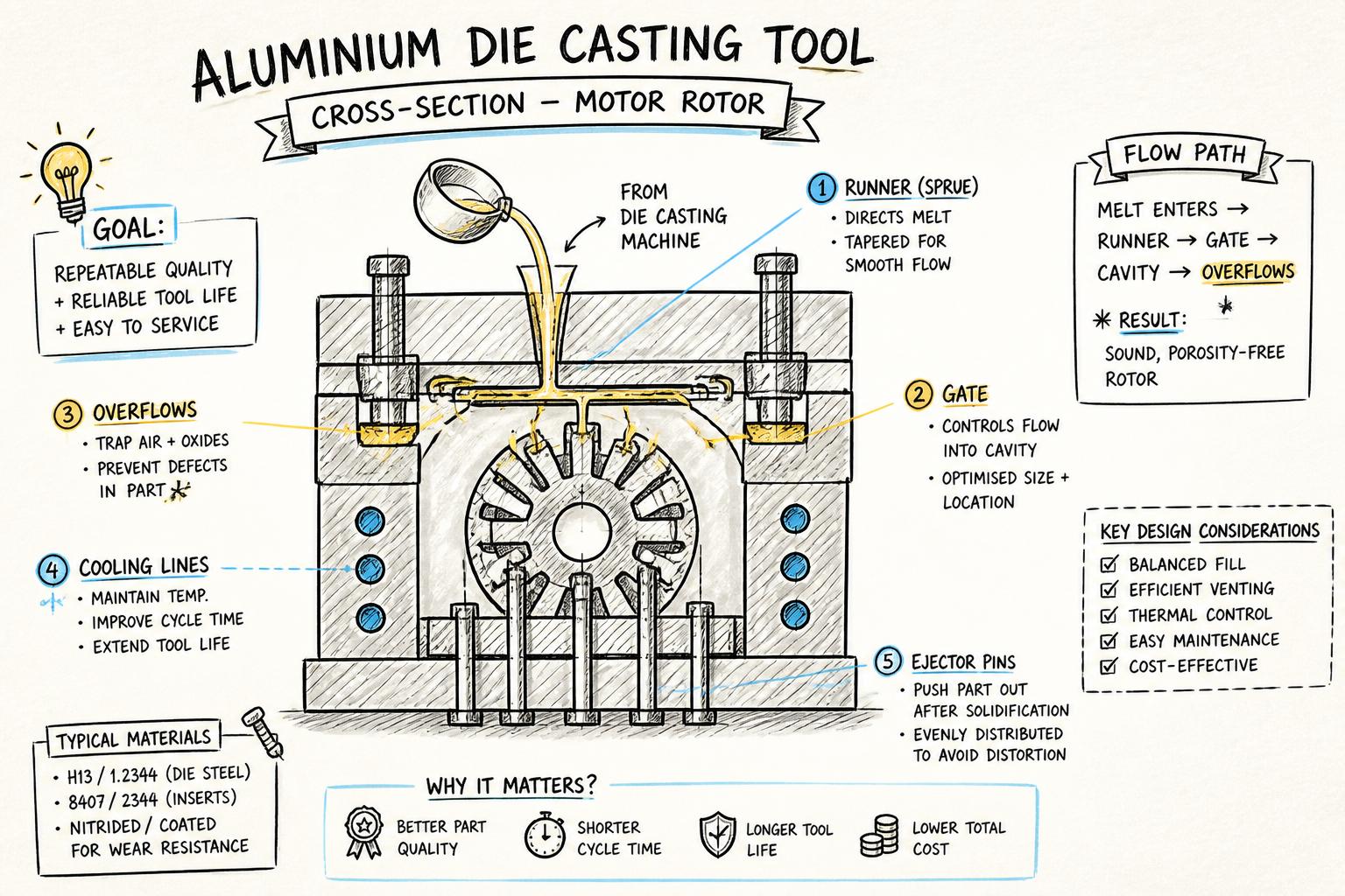
A typical aluminium die casting mold includes:
Fixed and moving halves – Define the part cavity and parting line.
Runners, gates, and overflows – Distribute molten metal, manage air evacuation, and capture impurities.
Cores and slides – Form internal features, undercuts, and complex geometries.
Cooling channels – Control solidification rate and reduce cycle time.
Ejector system – Pins or plates that push the solidified part out of the die.
Design choices that affect cast quality
From an OEM perspective, a few design decisions have outsized impact on die casting performance:
Wall thickness and transitions – Avoid abrupt changes that cause hot spots and porosity; use smooth fillets and gradual transitions.
Parting line location – Influences flash, machining stock, and ease of ejection.
Machined vs as-cast surfaces – Critical sealing or bearing areas should usually be machined; specify realistic as-cast tolerances elsewhere.
Vent and overflow locations – Allow air and impurities to escape without compromising functional surfaces.
For electric motor rotors, die design also interacts with downstream surge testing and dynamic balancing. Our article on quality controls in die casting explains how tooling, process parameters, and testing work together to ensure field reliability.
Tooling quotes can vary widely for what looks like the same part. Understanding tooling cost estimation helps you compare proposals on more than just headline price.
Major cost drivers
Tool complexity – Number of stations (stamping) or slides/cores (die casting), presence of sensors, and level of automation.
Tool size and steel volume – Larger parts, thicker plates, and higher press tonnage all increase material and machining time.
Tolerance and surface finish – Tighter specs may require finer machining, more complex inserts, or additional machining operations.
Expected volume and life – Tools designed for millions of strokes or shots need tougher steels, more robust guiding, and better cooling.
Validation and tryout – Number of sample lots, PPAP/ISIR requirements, and testing (e.g., Epstein testing for laminations, surge testing for rotors).
Organizations like SME (Society of Manufacturing Engineers) and NIST provide guidance on cost modeling and process capability that can help you interpret supplier quotes more critically.
Under-investing in tooling often leads to:
Higher scrap and rework rates
Frequent unplanned maintenance and downtime
Inability to hold tolerances as tools wear
Costly engineering changes when issues appear at SOP
Conversely, over-engineered tools may add cost without proportional benefit if your volumes or tolerance requirements do not justify them.
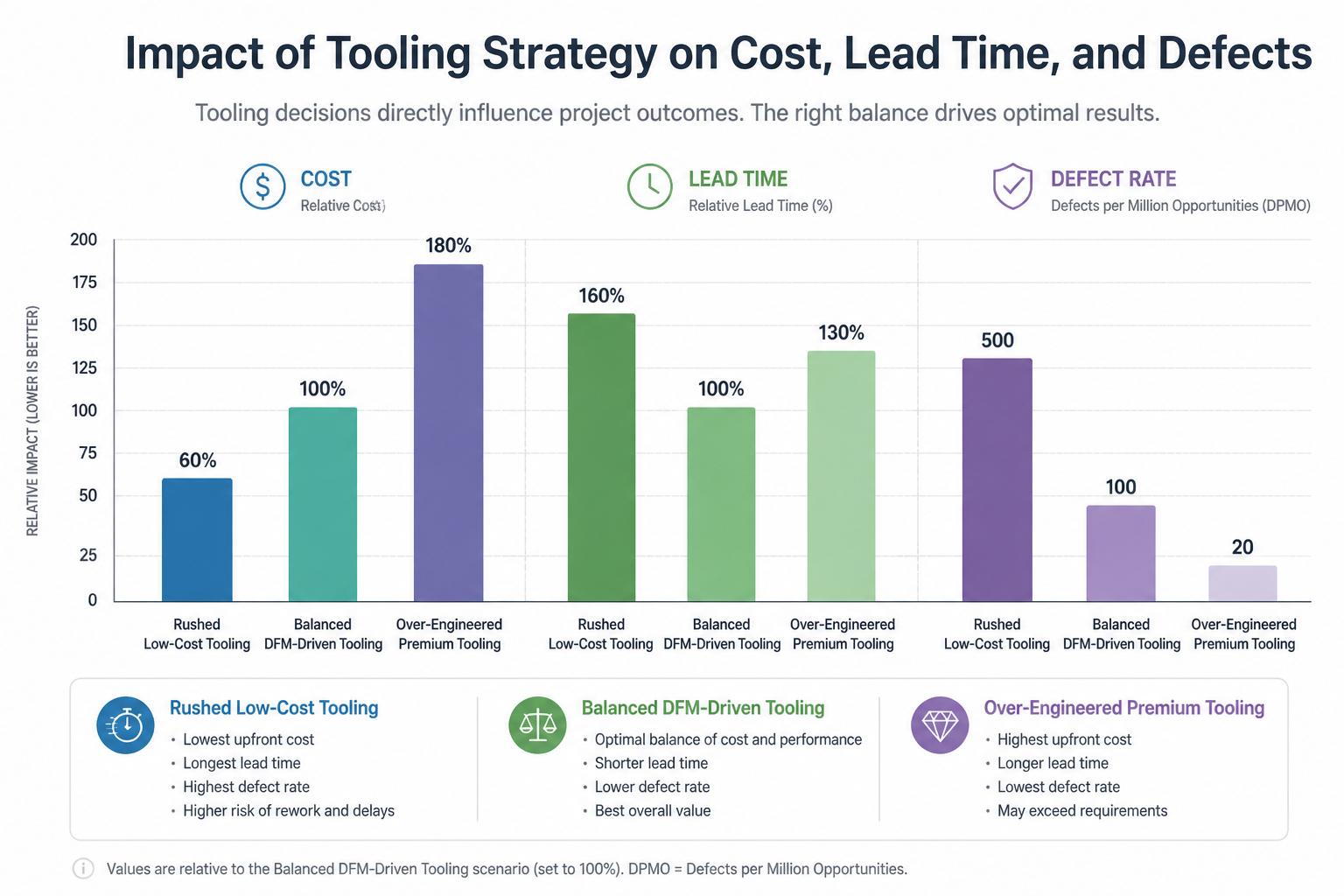
In practice, the best results usually come from a balanced, DFM-driven tooling concept that targets your real volume, quality, and launch risk profile.
Tool life optimization and maintenance in production
Once tools are in production, the focus shifts from design to tool life optimization. As an OEM engineer, you can influence this through realistic specifications and by choosing suppliers with strong maintenance capabilities.
Stable process windows – Consistent press settings, lubrication, and casting parameters reduce shock and thermal cycling.
Proper alignment and setup – Accurate die setting and press maintenance prevent uneven wear and chipping.
Condition monitoring – SPC on key dimensions, visual inspection, and sensor data help catch issues early.
Scheduled maintenance – Regrinding, polishing, and replacement of wear parts at defined intervals.
Integrating stamping, die casting, machining, and testing with one supplier can simplify this. Our article on integrated stamping, die casting, and machining supply explains how this reduces risk and lead time.
Precision tooling design is a collaborative exercise. The best outcomes come when OEM engineers, tooling designers, and manufacturing engineers align early.
Engage early with clear priorities
When you share a new part with a supplier like ASA Industries, include:
Volume and ramp profile – Expected annual volume, SOP date, and ramp-up curve.
Functional requirements – Which dimensions and surfaces truly matter for performance and assembly.
Testing and certification needs – PPAP level, special tests (Epstein, surge), and any customer-specific requirements.
Change flexibility – How likely design changes are before and after SOP.
This helps your supplier propose the right balance of tool complexity, automation, and modularity.
For important programs, request two or three tooling concepts with different trade-offs, such as:
Lower upfront cost, shorter life
Medium cost with modular inserts for future variants
High-capacity, highly automated tooling for long-term platforms
Compare not just the tooling price, but piece price, scrap assumptions, and maintenance expectations over the program life.
Putting it all together: a practical checklist for OEM engineers
Use this checklist when you are about to release a drawing or RFQ for a stamped or die-cast component:
Have I clearly identified function-critical features and allowed reasonable tolerances elsewhere?
Have I considered DFM for tooling—access, standardization, and adjustability—not just the part geometry?
Have I shared realistic volume and lifecycle expectations so the supplier can size tool life appropriately?
Have I invited early feedback from a stamping or die casting specialist on strip layout, gating, and cooling?
Do I understand how tooling decisions affect downstream quality controls like Epstein or surge testing?
Am I comparing tooling proposals on total cost of ownership, not just upfront price?
For OEMs building electric motors, appliances, and industrial equipment, stamping and die casting tools are long-lived assets that shape cost, quality, and supply risk for years. Treating precision tooling design as a core engineering discipline—not just a purchasing decision—helps you launch faster and run more reliably.
If you are planning a new motor or appliance program and want to align design, tooling, and manufacturing from the start, partner with a supplier that offers in-house tooling, progressive die stamping, aluminium die casting, CNC machining, annealing, and testing. That integration makes it far easier to optimise parts, tools, and processes together.
1 See, for example, cost-commitment curves discussed in design-for-manufacturing literature such as Boothroyd, Dewhurst, and Knight, Product Design for Manufacture and Assembly.