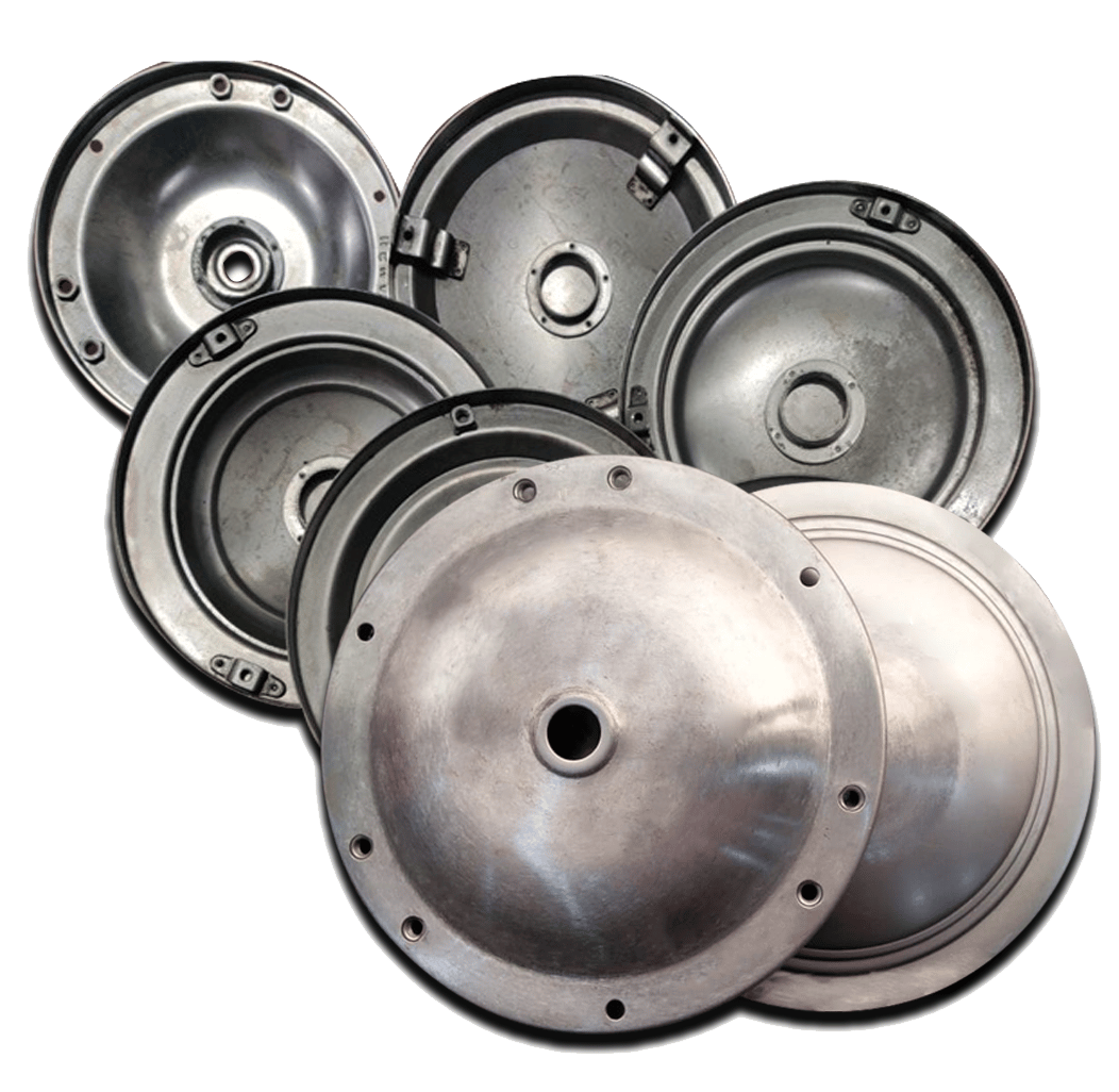
Electrical appliance OEMs rarely lose money on raw material. They lose it on rework, tooling changes, and line stoppages caused by sheet metal components that looked fine in CAD but fight every press, bender, and assembly jig on the shop floor.
This tutorial walks through how to design sheet metal components for electrical appliances so they run smoothly in stamping, bending, and finishing – and assemble the first time, every time.
We will focus on practical design-for-manufacturability (DFM) rules you can apply directly to appliance brackets, covers, motor housings, and electrical enclosures. For a deeper look at how these parts interact with motor laminations and magnetic cores, see our overview of electrical stamping fundamentals.
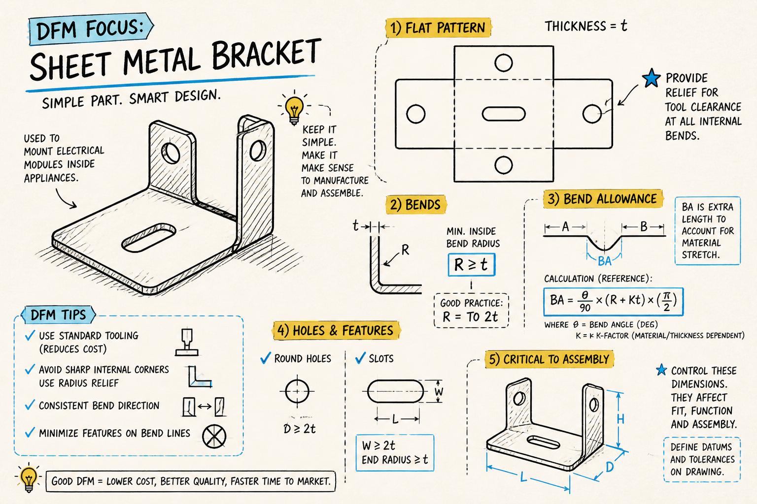
In most household and industrial appliances, sheet metal parts quietly do the hard work of:
Mounting motors, PCBs, and controls
Providing structural frames, brackets, and internal chassis
Forming enclosures and guards for safety and IP protection
Conducting or isolating heat around motors and power electronics
Providing electrical grounding paths and shielding
These appliance sheet metal parts are often produced in the same stamping cells that make rotor and stator laminations and other electrical stampings. That means your design choices directly affect die design, press selection, and overall line efficiency.
Before diving into dimensions and bend formulas, align your design with four core principles:
Standardise wherever possible: thicknesses, bend radii, hole sizes, and fasteners.
Design to the stamping process: avoid features that require secondary machining or hand operations.
Control variation, not perfection: specify only the tolerances and finishes that actually matter to function.
Think in sequences: picture how the flat blank is stamped, formed, finished, and assembled.
These principles are the same ones used to evaluate when progressive die stamping is justified for high-volume programs.
Step 1: Choose the right material and thickness
Material and thickness are your first DFM decisions. They determine press tonnage, tool life, and achievable bend radii.
CRCA mild steel (e.g., IS 513): general brackets, frames, covers.
Galvanised steel (GI): corrosion-resistant enclosures and outdoor units.
Stainless steel (SS304/SS430): food-contact surfaces, decorative panels, high corrosion areas.
Silicon steel: where the sheet metal component doubles as a magnetic path (less common but relevant near motors).
Aluminium: lightweight housings, fan guards, and thermal components.
Refer to reliable data sources like the MakeItFrom material database or steel supplier datasheets for yield strength and elongation, which influence formability.
Guidelines for choosing thickness
Use the minimum thickness that meets structural and stiffness needs to reduce cost and press load.
Avoid mixing many thicknesses within the same appliance platform; this complicates tooling and inventory.
Align with coil stock that your stamping partner already runs (e.g., 0.8, 1.0, 1.2, 1.6 mm) to avoid special ordering.
For parts that interface with magnetic cores and laminations, coordinate thickness to maintain air gaps and magnetic performance.
Step 2: Design with stamping in mind
Most industrial sheet metal fabrication for appliances is stamping-based, not laser-cut and brake-formed. That means your part should be easy to produce in a blanking and forming die, ideally in a progressive tool at volume.
Stamping-friendly geometry
Use round or slotted holes with standard punch sizes; avoid tiny notches and sharp internal corners that cause punch breakage.
Maintain minimum web widths between holes and edges (typically >= 1.5 × thickness) to prevent distortion and cracking.
Avoid extremely narrow tabs that are prone to bending or warping during handling.
Where possible, combine features (e.g., use a locating slot that also serves as a clearance for wiring).
Hole and feature positioning relative to bends
Holes too close to bend lines distort during forming and can cause assembly issues.
As a rule of thumb, keep holes at least 2 × material thickness away from the start of the bend zone.
For critical holes (e.g., motor mounting), increase this to 3–4 × thickness or place them in a flat area after bending.
If tight location is needed near a bend, consider re-strike or coining features in the tool, but weigh the added cost.
Step 3: Get bend radii and bending allowances right
Poorly chosen bend radii and incorrect flat patterns are a major source of rework for precision metal components.
Choosing practical bend radii
For most appliance parts, use these starting guidelines (verify with your stamping partner):
Mild steel: inside bend radius ≈ 1.0 × thickness for standard bends.
Stainless steel: inside radius ≈ 1.0–1.5 × thickness to reduce cracking.
Aluminium: inside radius ≈ 0.8–1.0 × thickness depending on alloy and temper.
More important than the exact value is consistency: standardise bend radii across your sheet metal components to simplify tooling.
Understanding bend allowance and K-factor
When you bend a sheet, the outer surface stretches and the inner surface compresses. The neutral axis sits somewhere in between, and its location is captured in the K-factor. This determines your bend allowance – how much material is consumed in the bend.
Incorrect bend allowances lead to flat patterns that are too long or too short, creating assembly gaps or forcing operators to "pull" parts into place.
Most CAD systems calculate bend allowance automatically, but you should still:
Use realistic K-factors validated with shop trials for each material and thickness.
Maintain a DFM library of tested bend tables shared between design and manufacturing.
Lock down bend parameters early for high-volume parts to avoid flat pattern changes after tooling is cut.
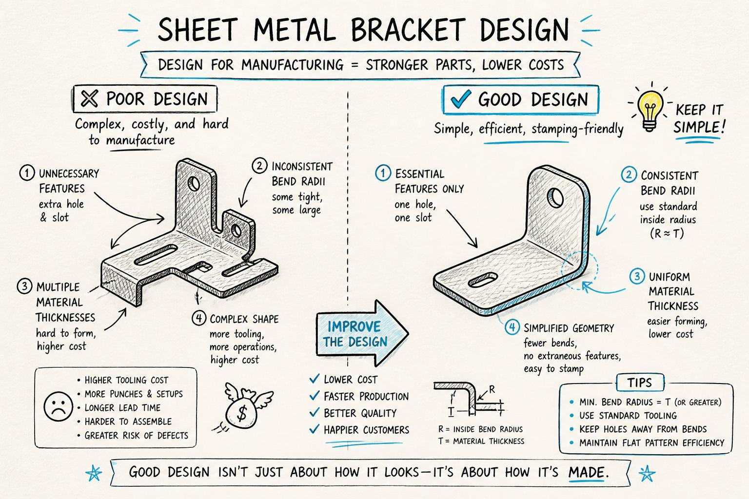
Step 4: Control tolerance stack up across assemblies
Most DFM discussions focus on individual features, but appliance failures usually come from tolerance stack up across multiple sheet metal parts, plastic mouldings, and motor components.
Map functional datums and interfaces
Identify primary functional datums: motor shaft centre, PCB connector face, door hinge axis, etc.
Relate critical sheet metal features (holes, slots, bends) back to these datums, not to random edges.
Use GD&T where it adds clarity, especially for position and perpendicularity of mounting features.
Designing for realistic stamping tolerances
Stamping can hold tight tolerances, but not everywhere and not for free.
Reserve the tightest tolerances for critical-to-assembly features and relax non-functional dimensions.
Use slots instead of tight round holes when you need adjustability to absorb stack up.
Discuss achievable tolerances with your stamping manufacturer in India before freezing the drawing.
Standards like ISO 2768 for general tolerances can provide a baseline, but you should still define critical features explicitly.
Step 5: Plan for finishing and coatings
Appliance sheet metal components almost always receive a surface finish: powder coating, painting, plating, or passivation. These processes introduce additional constraints.
Design considerations for powder coating and painting
Allow for coating thickness (typically 60–120 μm for powder coat) in holes and mating surfaces.
Use masking features (bosses, plugs, or dedicated masked areas) where electrical contact or grounding is needed.
Provide drain and vent holes to avoid liquid traps in pre-treatment and to ensure full coverage.
Design hanging or fixturing points that do not damage functional surfaces.
For components near motors and magnetic cores, finishes can affect both corrosion resistance and electrical behaviour.
Ensure that any insulating coatings do not interfere with grounding paths or EMI shielding.
Coordinate with motor and magnetic core manufacturing teams so that coatings do not create unintended air gaps or thermal barriers.
Follow relevant appliance and safety standards (e.g., IEC 60335 for household appliances) for creepage, clearance, and insulation.
Step 6: Design for assembly – not just fabrication
A perfectly stamped part that is slow or difficult to assemble is not a good design. DFM must go hand-in-hand with design for assembly (DFA).
Fast, fool-proof assembly features
Use self-locating features such as tabs and slots that snap parts into the right position before fastening.
Design symmetry or intentional asymmetry so parts cannot be assembled in the wrong orientation.
Minimise separate fasteners by using embossed forms, lances, or self-clinching hardware where appropriate.
Ensure sufficient finger clearance and tool access for operators or robots.
Sheet metal parts often interface with die-cast housings, plastic covers, and motor laminations.
Use slots and floating fasteners to accommodate variation between different manufacturing processes.
Provide datum features that can be probed or checked in fixtures for incoming inspection.
Where possible, design modular brackets that can be used across multiple appliance models with minor changes.
Good DFM often looks like "nothing happened" – the line runs smoothly, and quality issues are rare. Poor DFM shows up as chronic rework, extra fixtures, and emergency tooling modifications.
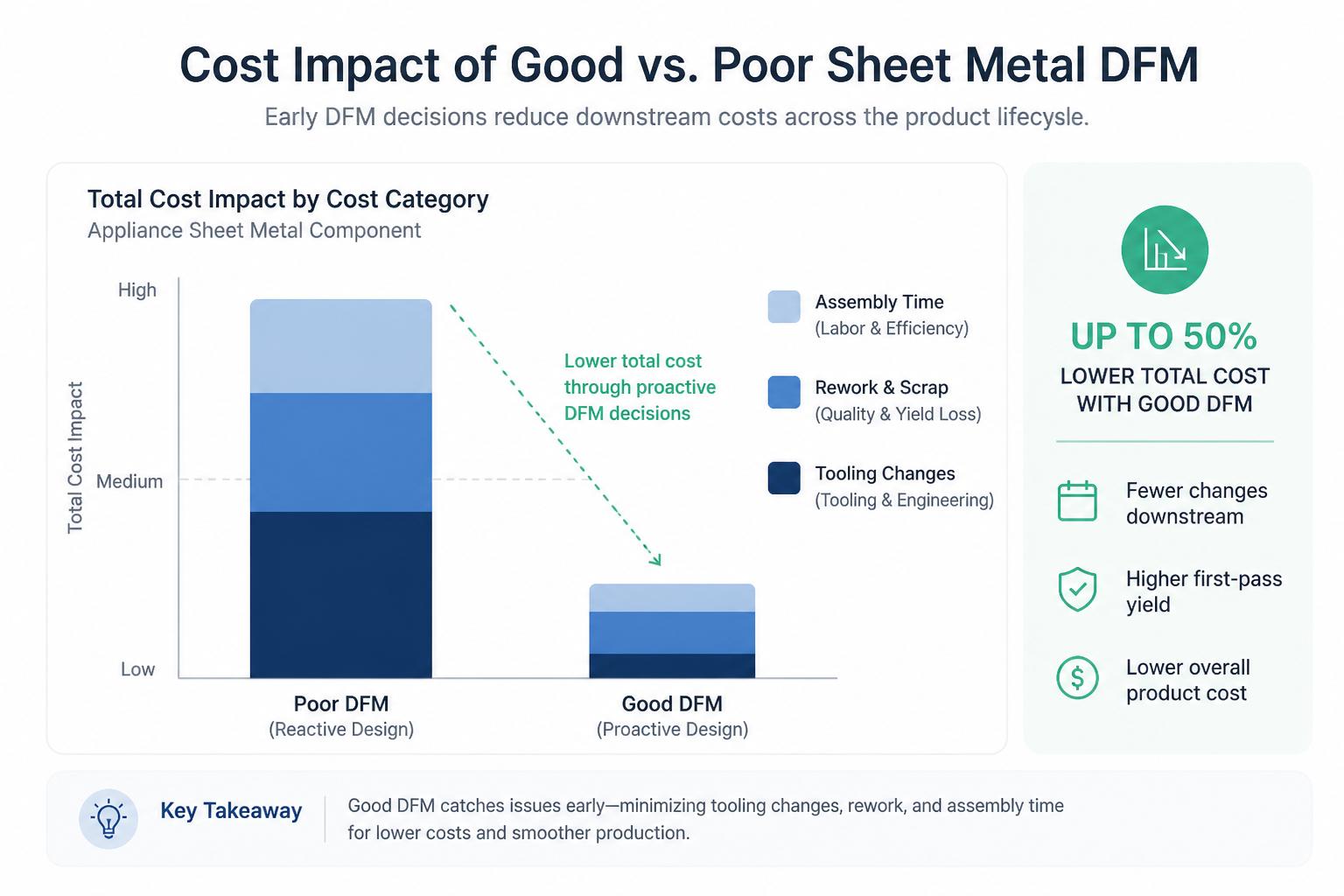
Across appliance programs, we typically see:
20–40% reduction in tooling change requests when DFM reviews are done before tool design.
10–25% lower assembly time when brackets and enclosures are designed with self-location and access in mind.
Significant scrap reduction when bend allowances are validated and hole-to-bend distances are respected.
Industry studies on DFM and DFA, such as those summarised by the U.S. NIST survey on DFM/DFA practices, consistently show that early design decisions have the largest leverage on total product cost.
How to work effectively with your stamping partner
Even the best internal design guidelines benefit from close collaboration with your stamping supplier.
Provide 3D models, 2D drawings, and expected annual volumes before freezing designs.
Discuss whether progressive, compound, or simple dies make most sense for each part family.
Ask for feedback on material utilisation and strip layout to reduce scrap.
Request DFM feedback, not just a quote
Encourage suppliers to highlight risk areas: tight hole-to-bend distances, very small features, or unrealistic tolerances.
Be open to design tweaks that save tooling stages or secondary operations.
Align on inspection plans for critical sheet metal components that affect motor performance or safety.
Use this concise checklist during design reviews for new or modified appliance parts:
Material and thickness align with existing coils and structural needs.
Geometry is stamping-friendly with standard holes and adequate web widths.
Bend radii are standardised and bend allowances validated.
Critical features are tied to functional datums with realistic tolerances.
Finishing and coating requirements are reflected in clearances and grounding paths.
Assembly sequence is simple, with self-locating features and good access.
Stamping partner has reviewed and approved the design for tooling.
Next steps
If you are developing a new appliance platform or refreshing an existing one, start by reviewing your highest-volume sheet metal components using the checklist above. Small design changes – a standardised bend radius, a relocated hole, a simplified bracket – can unlock major savings once parts are in mass production.
To go deeper into how your sheet metal parts interact with motor laminations, cores, and stamped electrical components, explore our guides on electrical stamping basics, designing rotor and stator laminations, and magnetic core manufacturing.
When you are ready to translate appliance designs into robust tooling and stable production, partnering with an experienced stamping manufacturer that understands both electrical and structural components will make the difference between constant firefighting and predictable, high-yield output.