When you choose die cast components for an electric motor, you’re locking in performance, cost, and reliability for the next decade of that product’s life. Get the material or specification wrong, and you inherit vibration issues, premature bearing failures, corrosion, or assembly headaches at scale.
This explainer walks through where die-cast parts make sense in motor design, how aluminium die casting actually works, and what OEMs must specify so suppliers in industrial manufacturing in India and elsewhere can deliver repeatable quality.
If you are also sourcing laminations and cores, you may want to read our guide to stator and rotor laminations design, losses, and sourcing alongside this article, because die cast housings and end-shields must work as a system with the magnetic stack.

Where die cast components fit in motor design
In most small and medium electric motors, die cast components are used wherever you need a complex, structural, non-magnetic part in medium-to-high volumes. Common examples include:
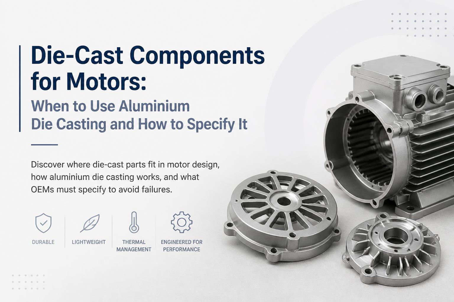
Motor housings and frames (especially for compact, enclosed motors)
End-shields / end-covers that locate bearings and close the stator stack
Fan covers and decorative ceiling fan motor parts (hubs, bottom covers, canopies)
Terminal boxes, brackets, mounting feet, and integrated cooling fins
Rotor cages in some induction motors (pressure die cast aluminium into rotor slots)
These parts sit alongside the magnetic stack, laminations, and cores. For a deeper view of how the magnetic side is built, see our overview of magnetic cores for electrical machines and performance trade-offs.
When die casting is the right choice
Aluminium die cast components are usually the best fit when you have:
Annual volumes above ~10,000 pieces per part number, so tooling cost is amortized
Complex geometry (fins, ribs, undercuts with slides, integrated bosses) that would be expensive to machine
Need for consistent dimensions across large batches, especially for bearing seats and assembly interfaces
Weight-sensitive designs (fans, domestic appliances, BLDC motors) where aluminium’s low density is an advantage
Good thermal conductivity requirements, e.g., housings with cooling fins for higher power density motors
For very low volumes, very large frames, or extremely high mechanical loads, alternatives like sand casting, fabricated steel housings, or fully machined components may be more appropriate.
Typical die cast parts in different motor types
Across motor families, die cast components appear in slightly different roles:
Single-phase induction motors: end-shields, fan covers, terminal boxes, sometimes capacitor housings
Brushless DC (BLDC) motors: rotor hubs, housings with integrated mounting features, stator carriers, fan blades
Universal motors: brackets, end-shields, small housings where weight and cost matter
Shaded pole motors: compact housings and mounting brackets in fans and small appliances
To see how these mechanical parts interact with the laminated stack, you can refer to our guide on electric motor components architecture and materials.
How aluminium die casting works (for motor OEMs)
From an OEM perspective, you don’t need to be a foundry expert, but understanding the basics of aluminium die casting helps you specify parts realistically and interpret what your supplier is telling you.
Process overview
In high-pressure aluminium die casting for motor parts, the basic steps are:
Tooling (die) design and manufacture – steel mould with cavity, cores, slides, runners, gates, vents, and cooling channels.
Melting and dosing – aluminium alloy is melted in a furnace and metered into a shot chamber.
High-pressure injection – molten metal is forced into the die cavity at high speed and pressure.
Solidification and cooling – metal cools in the die, controlled by cooling lines and cycle time.
Ejection – part is ejected, runners and overflows are removed.
Trimming, machining, and finishing – flash removal, critical surfaces machined, surface treatment applied if needed.

What this means for design and specification
Because metal is injected into a steel die under pressure, the process has some important implications:
Excellent repeatability – good for tight fits (e.g., bearing bores) when combined with post-machining.
Draft angles are mandatory – vertical walls need taper to allow ejection (often 1–3°).
Uniform wall thickness is preferred – thick-to-thin transitions can cause porosity and distortion.
Sharp corners are discouraged – fillets reduce stress and improve metal flow.
Large flat areas may warp – ribs, bosses, or design tweaks help maintain flatness.
Standards such as NADCA die casting design guidelines provide detailed recommendations on draft, wall thickness, and radii that your supplier will typically follow.
Aluminium vs other materials for motor die cast components
Aluminium is not the only option for die cast components, but it is the most common in small and medium motor applications.
Why aluminium die casting is widely used
For motor OEMs, aluminium offers a combination of properties that are hard to beat:
Low density – lighter motors, easier installation, lower shipping cost.
Good thermal conductivity – helps move heat out of the stator and windings.
Corrosion resistance – especially with suitable alloys and surface treatments.
Non-magnetic – avoids distortion of the machine’s magnetic field.
Excellent castability – fills thin fins, small bosses, and intricate shapes.
In industrial manufacturing in India, common pressure die casting alloys include ADC12 / Al-Si-Cu equivalents and AlSi9Cu3, selected for flowability and mechanical properties. For detailed mechanical data, see references like the MatWeb datasheet for ADC12 aluminium alloy.
Alternatives: when aluminium die casting is not ideal
Cast iron housings – better for very heavy-duty industrial motors where stiffness and vibration damping are paramount, but heavier and not suitable for high-speed thin fins.
Fabricated steel frames – used in large-frame motors where die casting tooling would be uneconomical.
Magnesium die casting – lighter than aluminium but more expensive and with stricter handling and corrosion considerations.
Plastic injection moulding – viable for non-structural covers and fan blades but lacks thermal and mechanical performance for housings.

Designing motor parts for aluminium die casting
Good die cast design starts from the function of the motor component, then works backward to geometry that is casting-friendly. The earlier your supplier is involved, the more cost and weight you can remove.
Key design principles
Maintain uniform wall thickness where possible (e.g., 2.5–4.0 mm for many housings) and avoid sudden jumps.
Use ribs instead of thick sections to achieve stiffness while keeping weight and porosity under control.
Add proper draft on all die-pull faces; confirm direction of die opening early in the design.
Round internal and external corners with appropriate radii to improve metal flow and fatigue life.
Plan machining allowances on bearing bores, gasket faces, and critical interfaces.
Consider assembly – integrate bosses, slots, and locating features to reduce secondary operations.
For motor laminations and stacks that will be housed in these parts, our article on progressive die stamping for motor laminations explains how lamination tolerances and burrs influence the required clearance in housings and end-shields.
Common die cast motor components and design notes
End-shields / bearing brackets
Function: locate bearings, close the stator, and provide mounting points.
Critical areas: bearing bores (usually machined), bolt-hole patterns, gasket faces.
Design tips: add ribs around bearing pockets, avoid overly thin webs between bolt holes and edges.
Motor housings / frames
Function: hold the stator stack, provide structural backbone, and dissipate heat.
Critical areas: stator bore, mounting feet, interface to end-shields.
Design tips: use external fins for cooling, ensure enough draft in the bore, and allow for machining of stator fit surfaces if needed.
Fan covers and decorative parts (e.g., ceiling fans)
Function: safety, airflow direction, and aesthetics.
Critical areas: mounting interfaces, balance, surface finish.
Design tips: keep walls thin and uniform, design for minimal secondary finishing, consider paint or powder-coat requirements.
What OEMs must specify for die cast components
Many failures in die cast motor parts are not “casting problems” but “specification problems”. If you only send a 3D model and ask for a quote, you are leaving major decisions to the supplier, which can lead to inconsistent results across vendors.
A robust specification for die cast components should cover at least the following:

1. Geometry and interfaces
Fully dimensioned drawings with datum structure and GD&T where appropriate.
Clear identification of critical-to-function dimensions (e.g., bearing bore, stator seat, mounting feet).
Explicit indication of which surfaces are as-cast and which will be machined.
Assembly drawings showing how the part interacts with laminations, shafts, seals, and fasteners.
2. Alloy and mechanical properties
Specify the alloy designation (e.g., ADC12 / AlSi9Cu3) or performance requirements (yield strength, elongation, hardness).
Define any corrosion resistance needs (e.g., coastal environments, chemical exposure).
State if heat treatment is required (many pressure die cast alloys are used as-cast, but some applications may demand special treatment).
Alloy selection affects castability, porosity, and machinability. Authoritative sources like the Copper Development Association and aluminium alloy handbooks provide comparative property data that can inform your choice.
3. Dimensional tolerances and GD&T
Use realistic casting tolerances for as-cast features based on die casting capability tables.
Tighten tolerances only on functional features and, where possible, achieve them by machining.
Define position, concentricity, and flatness requirements using GD&T symbols rather than over-tolerancing linear dimensions.
Specify function, interfaces, and critical-to-quality parameters. Let the supplier optimise non-critical features for manufacturability and cost.

4. Surface finish and coatings
Define surface roughness where it matters (e.g., gasket faces, sealing surfaces).
Specify cosmetic requirements for visible parts (e.g., ceiling fan covers): acceptable porosity size, flow lines, and paint coverage.
State coating type and thickness: powder coating, anodizing, electrophoretic deposition (ED), or others.
5. Quality checks and testing
For critical motor components, your drawing or specification should define:
Dimensional inspection plan: sampling frequency, CMM checks, and key characteristics.
Porosity control requirements: X-ray, pressure testing, or impregnation if needed.
Mechanical tests (if required): hardness, tensile tests on separately cast samples.
Functional tests: fitment trials with laminations, shafts, and assembled motors.
For parts that directly impact magnetic performance (e.g., rotor cages, integrated cores), align your test plan with the principles discussed in our article on annealing motor laminations and quality checks.
6. Logistics, packaging, and lifecycle
Define packaging method to prevent damage to machined faces and painted surfaces.
Specify stacking limits and handling instructions, especially for thin fins and decorative covers.
Clarify lifecycle expectations (e.g., number of on/off cycles, environmental conditions) so the supplier can advise on alloy and coating choices.
Common failure modes in die cast motor components (and how to avoid them)
Understanding typical issues helps you build preventive measures into your specifications and supplier audits.
1. Porosity and leaks
Symptoms: oil leakage, pressure loss in sealed housings, weak threads, or paint defects.
Root causes: trapped air, poor venting, turbulent metal flow, or excessive wall thickness.
Prevention:
Design for uniform walls and smooth transitions.
Agree on acceptable porosity level and inspection methods.
Use impregnation only when necessary; better to fix design and process.
2. Dimensional instability and warpage
Symptoms: misalignment of bearings, noisy operation, rotor-stator rubbing, difficult assembly.
Root causes: uneven cooling, large flat areas without ribs, excessive internal stresses.
Prevention:
Introduce ribs and gussets to support flat surfaces.
Allow realistic flatness tolerances and machining on critical faces.
Review die cooling layout and gating with the supplier during development.
3. Corrosion and coating failures
Symptoms: blistering paint, white corrosion products, pitting on outdoor or coastal installations.
Root causes: unsuitable alloy, inadequate surface preparation, or mismatched coating system.
Prevention:
Select alloys and coatings suitable for the environment.
Specify pre-treatment (e.g., chromate-free conversion coatings) before painting.
Include salt spray or humidity tests in qualification for outdoor applications.
Partnering with a die casting supplier for motor components
For OEMs, the best results come when the die casting supplier is involved early in the motor design process, alongside your lamination and magnetic core partners.
What to look for in a supplier
Experience with electric motor components – understanding of bearing fits, stator stack interfaces, and dynamic balance.
In-house tooling design and maintenance – faster design-for-manufacture feedback and better control of dimensional stability.
Integrated machining and finishing – single-source responsibility for critical dimensions and surface quality.
Process control and traceability – documented parameters for melting, injection, and cooling; material certificates.
Ability to supply related components – laminations, magnetic cores, and sheet metal parts for a complete motor component set.
Manufacturers like ASA Industries combine die cast components with stator and rotor laminations, magnetic cores, and sheet metal parts, simplifying your supply chain and reducing interface risk between structural and magnetic elements.
Summary: When and how to use aluminium die cast components in motors
Aluminium die casting is a powerful enabler for modern motor design, especially in high-volume applications like fans, pumps, appliances, and compact industrial drives. It delivers complex shapes, good heat dissipation, and consistent quality at competitive cost.
To capture those benefits, OEMs should:
Use die casting where volumes, complexity, and weight justify tooling investment.
Design parts with casting-friendly geometry: uniform walls, draft, ribs, and proper radii.
Specify alloy, tolerances, surfaces, and test plans explicitly, focusing on critical-to-quality features.
Align die cast housings and end-shields with lamination and magnetic core designs from the start.
Work with experienced suppliers who understand the full motor system, not just individual parts.
If you’re reviewing your current motor platform or planning a new one, now is the right time to reassess which components should be die cast, which should be stamped or machined, and how a more integrated sourcing strategy can reduce cost and improve reliability across your product line.