When an electric motor runs hotter, noisier, or less efficiently than expected, the problem is often hidden deep inside the magnetic core. The design and quality of stator and rotor laminations quietly decide how much energy becomes useful torque—and how much is lost as heat and vibration.
This explainer walks through how lamination geometry, electrical steel grade, and manufacturing quality affect core losses, noise, and lifecycle cost. You will also find practical sourcing guidelines you can use when evaluating any motor lamination manufacturer, especially in high-volume, cost-sensitive applications.
For a broader view of how laminations fit into the motor as a whole, you can also refer to our guide on electric motor components and architecture.

What are stator and rotor laminations?
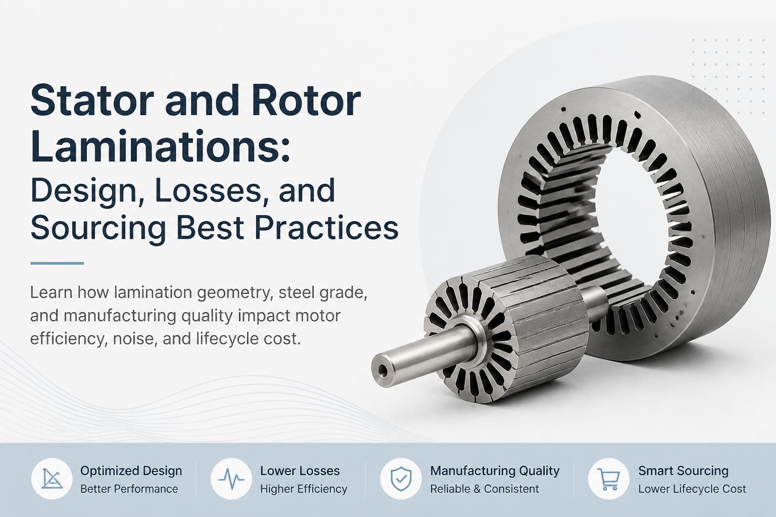
In most AC and DC motors, the magnetic core is not a solid piece of steel. Instead, it is built from a stack of thin, insulated sheets of electrical steel called laminations. These laminations are stamped into precise shapes for the stator (stationary part) and rotor (rotating part) and then stacked to form the complete core.
The purpose of laminations is twofold:
How you design and manufacture these laminations has a direct impact on motor performance, efficiency, acoustics, and cost. We cover core material choices in more depth in our article on magnetic cores for electrical machines.
Core losses in laminated stators and rotors
Two main types of losses dominate in stator and rotor laminations:
1. Eddy current losses
When the magnetic field in the core changes (as it does every electrical cycle), it induces circulating currents in the steel. These eddy currents flow in loops within the material, generating heat and wasting power.
Laminations limit eddy currents by:
Reducing thickness: Thinner laminations mean smaller loops and lower eddy currents.
Adding insulation: Each sheet is coated with an insulating layer so current cannot easily flow between laminations.
Using high-resistivity steel: Silicon-alloyed electrical steels have higher resistivity than plain carbon steel, reducing current flow.
2. Hysteresis losses
Hysteresis losses arise from the energy required to magnetize and demagnetize the steel each cycle. They depend mainly on:
Material grade and microstructure (e.g., grain-oriented vs. non-grain-oriented electrical steel).
Peak flux density in the core—running closer to saturation increases losses.
Operating frequency—losses grow with frequency.
Authoritative data sheets for electrical steels, such as those from AK Steel (Cleveland-Cliffs) or Tata Steel electrical steels, provide core-loss curves that help you quantify these effects.
How lamination thickness and steel grade affect losses
You can think of lamination design as a trade-off between material cost, manufacturing complexity, and performance. Two critical levers are lamination thickness and steel grade.

Lamination thickness
Common thicknesses for stator and rotor laminations include:
0.50–0.65 mm for low-cost, low-speed industrial motors.
0.35–0.50 mm for general-purpose motors and many appliance motors.
0.20–0.35 mm for high-efficiency, high-speed, or EV traction motors.
Thinner laminations reduce eddy current losses but require more precise precision stamping, tighter tooling tolerances, and often higher-grade steel. This typically increases material and manufacturing cost but can significantly improve efficiency and temperature rise.
Electrical steel grade
Most stator and rotor laminations are made from non-grain-oriented (NGO) electrical steel, optimized for rotating machines. Key parameters include:
Silicon content (typically 1.0–3.5%), which increases resistivity and reduces losses.
Grade designation (e.g., M19, M27, or equivalent), which bundles thickness and loss characteristics.
Coating type (inorganic, organic, or hybrid) that affects interlaminar insulation and punchability.
Higher-grade steels with lower core losses cost more per kilogram but can reduce the size of the motor, lower copper usage, and improve efficiency. A lifecycle-cost analysis often shows that investing in better steel and lamination design pays back quickly through energy savings, especially for continuously running motors.
Key design features of stator and rotor laminations
Beyond thickness and material, the geometry of stator and rotor laminations strongly influences performance, noise, and manufacturability.
Stator lamination design
Important features of stator laminations include:
Outer diameter and inner diameter: Define the frame size and air gap.
Slots and teeth: Number, shape, and pitch determine winding layout, leakage inductance, and torque ripple.
Slot openings: Affect ease of winding insertion, cogging torque, and noise.
Skewing: Slight angular shift of slots between laminations reduces cogging torque and acoustic noise.
Ventilation features: Punch-outs or ducts that help cooling in larger machines.
Small changes in tooth width, slot geometry, and skew angle can dramatically alter torque ripple and acoustic behavior. Noise-sensitive applications like ceiling fans and HVAC blowers often require tight control over these parameters, along with consistent stacking quality.
Rotor lamination design
Rotor laminations differ by motor type, but key considerations include:
Squirrel-cage induction rotors: Slot shape and depth, end-ring design, and skewing to balance starting torque, efficiency, and noise.
Permanent magnet rotors (BLDC, PMSM): Magnet pockets, bridges, and barriers to control flux, mechanical strength, and demagnetization risk.
Universal and shaded-pole motors: Specialized pole shapes and shading rings for desired speed–torque characteristics.
For a deeper dive into how different motor types use laminations and other components, see our overview of die-cast components in motors and their interaction with laminations.
Manufacturing stator and rotor laminations
The best lamination design can still underperform if manufacturing quality is poor. Three areas matter most: stamping process, tooling design, and post-processing such as annealing and stacking.
Progressive die stamping vs. other methods
High-volume lamination production typically uses progressive die stamping, where a continuous strip of electrical steel passes through multiple stations in a single press stroke. Each stroke performs operations such as piercing, notching, and final blanking.
This approach offers:
High speed (hundreds of strokes per minute) for large production runs.
Excellent repeatability and dimensional control when tooling is well-designed and maintained.
Lower scrap per part with optimized strip layout.
We explain the method and its advantages in detail in our article on the progressive die stamping process for motor laminations.

Tooling for motor laminations
Tooling quality is a primary differentiator between lamination suppliers. Good tooling for motor laminations ensures:
Tight dimensional tolerances on slot width, tooth width, and outer/inner diameters.
Minimal burr height to avoid shorted laminations and assembly issues.
Optimized strip layout for material yield and cost efficiency.
Long die life and predictable maintenance intervals.
Many OEMs underestimate the impact of tool design and maintenance on core losses. Excessive burrs and mechanical deformation can locally short-circuit laminations, increasing eddy currents and noise. When evaluating suppliers, ask about in-house tool design capability, EDM and grinding infrastructure, and preventive maintenance practices.
Annealing and stress relief
Stamping introduces mechanical stresses and slight work hardening into the steel, which can degrade magnetic properties. A controlled annealing process restores permeability and reduces core losses.
Key parameters to control include:
Soak temperature and time appropriate to the steel grade and coating.
Protective atmosphere (e.g., nitrogen, hydrogen mix) to avoid oxidation.
Cooling rate to prevent warping or unwanted phase changes.
We discuss these aspects and relevant quality checks in our guide to annealing motor laminations.
Stacking, bonding, and core assembly
Once stamped, laminations are stacked to form the stator and rotor cores. Common methods include:
Interlocking (self-riveting) tabs formed during stamping.
Welding at selected points or around the circumference.
Bonding using specialized varnishes or adhesives.
Stacking quality affects:
Effective stack length and air-gap uniformity.
Mechanical balance, especially critical for high-speed rotors.
Noise and vibration from unbalanced or misaligned stacks.
For high-speed applications, bonded stacks can offer lower noise and better mechanical integrity, though at higher process complexity and cost.
Design considerations by application
Different motor applications prioritize different trade-offs in lamination design and sourcing.
Ceiling fans and small appliances
For ceiling fans, mixers, and similar appliances, OEMs often focus on:
Low acoustic noise and smooth operation.
Moderate efficiency at competitive cost.
High-volume production with consistent quality.
Here, stator and rotor laminations typically use mid-range NGO steels and thicknesses around 0.5 mm, with carefully optimized slot shapes and skewing to minimize hum and vibration.
Industrial motors and pumps
Industrial motors, pumps, and compressors often run continuously and consume significant energy. For these, the priorities shift toward:
High efficiency to meet IE3/IE4 standards and reduce operating cost.
Thermal management to handle continuous duty at elevated temperatures.
Reliability and long life under varying loads and environments.
Better steel grades, thinner laminations, and rigorous annealing become more attractive as their cost is offset by energy savings over the motor’s lifetime. Standards such as IEC 60034-30-1 efficiency classes provide a framework for these decisions.
High-speed and EV traction motors
In high-speed and traction applications, designers push materials and manufacturing to their limits:
Very thin laminations (0.20–0.27 mm) to control high-frequency losses.
Advanced NGO or even amorphous steels for minimal core losses.
Precision rotor balancing and robust bonding or welding methods.
Here, working with a supplier experienced in advanced electric motor core design and validation is essential to avoid costly iterations and field issues.
How to evaluate a motor lamination manufacturer
Whether you are sourcing from India or elsewhere, choosing the right partner for stator and rotor laminations can make or break your motor program. Beyond price, consider the following factors.
1. Technical capability and experience
Look for evidence that the supplier understands both manufacturing and application engineering:
Experience across multiple motor types (single-phase induction, BLDC, universal, shaded pole).
Ability to support electric motor core design reviews and DFM (design for manufacturability).
In-house tooling design and manufacturing, not just tool maintenance.
A partner like ASA Industries, with decades in industrial manufacturing in India and a focus on electrical machine components, can often propose design tweaks that reduce cost or improve performance before you freeze your drawings.
2. Process capability and infrastructure
Key questions to ask potential suppliers:
What stamping presses and speeds can you support for my part size and thickness?
Do you use high-speed precision stamping with coil-fed lines and automatic stacking, or mostly manual operations?
What is your typical burr height, and how do you monitor and control it?
Do you have in-house annealing furnaces with controlled atmosphere and documented recipes?
For a more complete view of how lamination production fits into the broader magnetic core supply chain, see our guide on magnetic cores for electrical machines.
3. Quality systems and testing
A robust quality system is critical for consistent motor performance. Look for:
Incoming material inspection, including steel grade verification and coating checks.
In-process dimensional and burr measurements with SPC where appropriate.
Core loss testing on representative stacks or Epstein samples.
Traceability from coil to finished core.
Suppliers who can correlate their internal test data with your motor performance metrics add significant value during development and ramp-up.
4. Supply chain reliability and scalability
Finally, consider how well the supplier can support your growth and delivery expectations:
Multiple manufacturing units or lines to provide redundancy and capacity.
Proven on-time delivery performance and inventory management.
Ability to scale from pilot runs to full production without compromising quality.
For OEMs looking to diversify or localize their supply base, partnering with an established Indian manufacturer that combines high-speed stamping, annealing, and die-cast component capability can simplify logistics and vendor management.
Putting it all together: best practices for stator and rotor laminations
To summarize, here are practical guidelines you can apply in your next motor program:
Align lamination design with application priorities. Decide early whether efficiency, noise, cost, or size is the main driver, and choose lamination thickness and steel grade accordingly.
Optimize geometry, not just material. Use FEA and prototyping to refine slot shapes, tooth widths, and skewing. Small geometric changes can reduce noise and losses without major material cost increases.
Invest in tooling and process capability. High-quality progressive dies, controlled precision stamping, and proper annealing often deliver better ROI than simply upgrading steel grade.
Specify measurable quality parameters. Include burr height limits, dimensional tolerances, core loss targets, and stacking factor in your drawings and supplier agreements.
Choose suppliers with integrated capabilities. A partner who can provide laminations, magnetic cores, and related die-cast motor components reduces interfaces and speeds up development.
Thoughtful design and sourcing of stator and rotor laminations is one of the most effective ways to unlock higher efficiency, quieter operation, and lower lifecycle cost in your motors. If you are evaluating new programs or looking to benchmark your current lamination strategy, engaging early with an experienced motor lamination manufacturer can reveal improvement opportunities that are otherwise easy to miss.