Energy efficiency targets are tightening, customers expect quieter machines, and every watt of loss in your motor or transformer ends up as heat you need to manage. In that context, the magnetic core is no longer a commodity steel stack – it is one of your biggest design and sourcing levers.
If you are comparing suppliers or evaluating a magnetic cores manufacturer, you need to understand how materials, lamination quality, and core topologies translate into losses, noise, and total cost. This explainer walks through the essentials so engineering, sourcing, and quality teams can speak the same language.
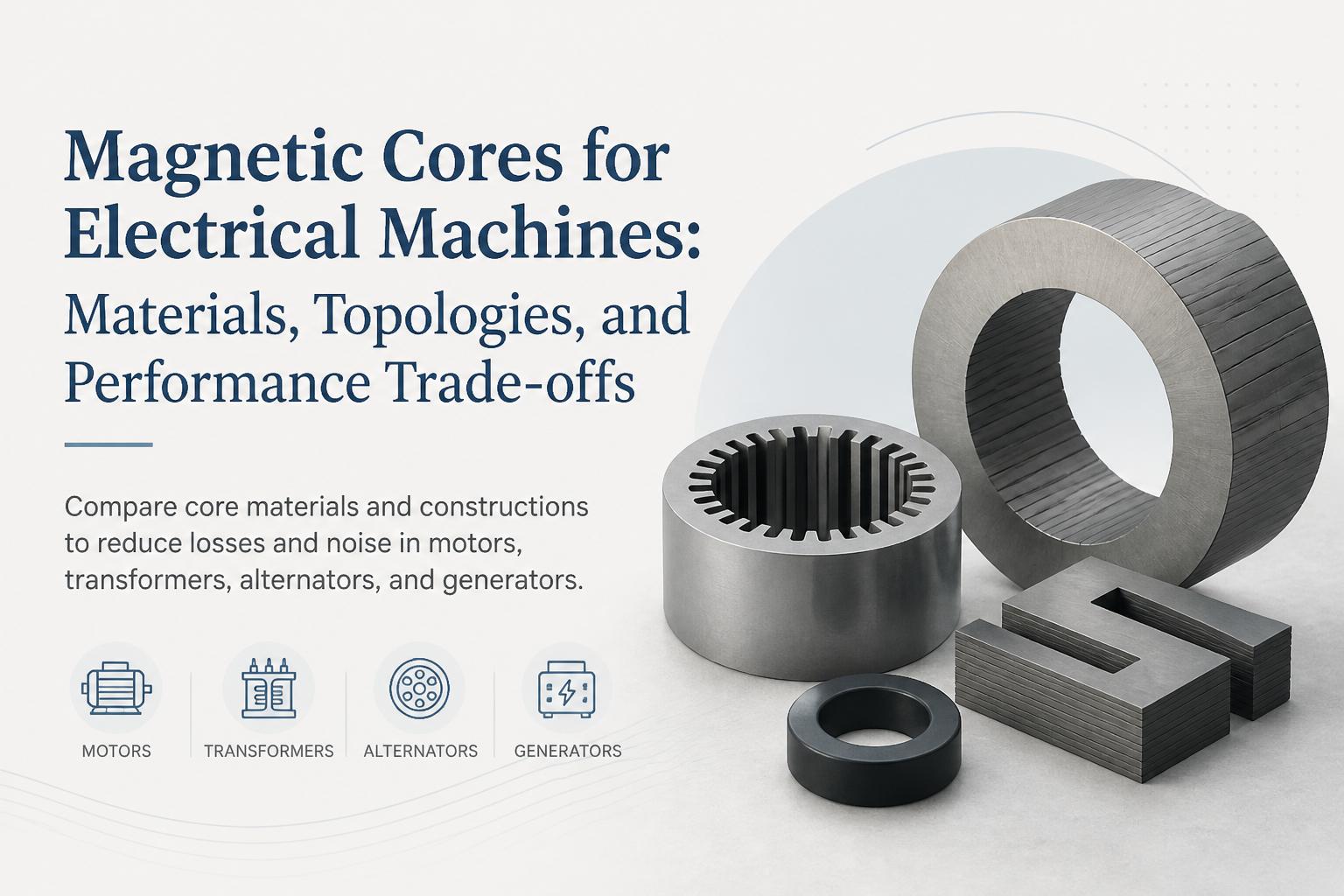
We will compare common core materials, look at topologies for motors, transformers, alternators, and generators, and highlight the manufacturing decisions that separate high-performance cores from average ones. For a deeper dive into how lamination geometry and stamping precision affect motors, see our guide to stator and rotor laminations design, losses, and sourcing.

What magnetic cores actually do in electrical machines
Magnetic cores provide a low-reluctance path for magnetic flux, allowing you to transfer energy efficiently between electrical and mechanical domains (motors, generators) or between windings (transformers, inductors).
In practice, the core must balance three competing needs:
High permeability to carry flux with minimal magnetizing current
Low losses (hysteresis + eddy current) over the operating frequency range
Mechanical and dimensional stability so performance stays consistent through stamping, stacking, impregnation, and service life
The wrong material or poor-quality laminations increase core losses, heat, and noise, and can force you to oversize copper and cooling systems. The right core design lets you hit efficiency targets with less copper, smaller frames, and quieter operation.
Key magnetic loss mechanisms you are fighting
Before comparing materials and topologies, it helps to separate the two main loss components inside a magnetic core. These losses appear as heat and directly reduce efficiency.
Hysteresis loss
Hysteresis loss comes from the energy required to flip magnetic domains every cycle. It depends on:
Soft magnetic materials with narrow hysteresis loops (like quality electrical steels and amorphous metals) have lower hysteresis loss. Operating closer to saturation or using lower-grade steel increases this loss.
Eddy current loss
Eddy currents are circulating currents induced in the core material by changing magnetic flux, as described by Faraday’s law. They scale roughly with:
Laminating the core, using appropriate insulation coatings, and choosing materials with higher resistivity are the main ways to control eddy current loss. Our article on progressive die stamping for motor laminations explains how tooling and stamping quality influence lamination thickness and burrs, which directly affect eddy currents.

Common magnetic core materials and when to use them
Most OEMs work with a small set of soft magnetic materials. The right choice depends on frequency, power level, efficiency targets, and cost constraints. Data in this section is based on typical values from electrical steel industry references and leading material suppliers.
Non-oriented electrical steel (NOES)
Non-oriented electrical steel is the workhorse material for rotating machines and many power transformers.
Applications: Induction motors, BLDC motors, alternators, generators, small and medium transformers
Frequency range: 50/60 Hz up to a few hundred Hz (higher with thinner gauges and optimized grades)
Advantages: Good balance of cost, mechanical strength, and magnetic performance; isotropic properties simplify rotor and stator design
Considerations: Grade selection (e.g., 50A600 vs higher-grade low-loss steels) has a large impact on core losses and material cost
For many industrial motors, the main trade-off is between a lower-cost grade with higher losses and a premium low-loss grade that allows you to downsize frame or copper. Our article on electric motor components architecture and materials discusses how this decision interacts with slot geometry, winding fill, and cooling.
Grain-oriented electrical steel (GOES)
Grain-oriented electrical steel is engineered so that magnetic properties are optimized in one rolling direction, making it ideal for transformer cores where flux largely flows in a controlled path.
Applications: Power and distribution transformers, large reactors
Frequency range: 50/60 Hz (designed for low-frequency, high-efficiency operation)
Advantages: Very low core losses along the rolling direction, enabling high-efficiency transformers
Considerations: Requires careful core cutting and stacking to maintain grain orientation; not suitable for rotating fields
When evaluating a magnetic cores manufacturer for transformer core laminations, their ability to control cutting angle, step-lap joints, and burr height is just as important as the steel grade itself.
Ferrites
Ferrites are ceramic, high-resistivity materials widely used in high-frequency magnetics.
Applications: SMPS transformers, high-frequency inductors, EMI filters, some high-speed motor applications
Frequency range: Tens of kHz to MHz
Advantages: Very low eddy current losses at high frequency due to high resistivity; good for compact, high-frequency designs
Considerations: Brittle, lower saturation flux density than electrical steels; generally not used for large rotating machines
Amorphous and nanocrystalline alloys
Amorphous metals (metallic glasses) and nanocrystalline alloys offer some of the lowest core losses available today, especially at higher frequencies.
Applications: High-efficiency transformers, high-frequency inductors, specialized motors and generators
Frequency range: 50/60 Hz up to tens of kHz depending on alloy and thickness
Advantages: Extremely low hysteresis and eddy current losses; can significantly reduce no-load losses
Considerations: Higher material cost, more complex processing, and sometimes limited mechanical robustness
According to studies summarized by the International Energy Agency, improving transformer core materials from conventional GOES to amorphous alloys can cut no-load losses by 60–70% in some applications, with a clear payback in high-duty-cycle grids.
Powdered iron and soft magnetic composites (SMC)
Powdered iron and SMCs are used where 3D flux paths or very high frequencies make traditional laminations less effective.
Applications: High-frequency motors, specialized actuators, compact inductors
Advantages: Isotropic 3D magnetic behavior, good high-frequency performance, design freedom for complex shapes
Considerations: Lower permeability and saturation compared to electrical steel; process control is critical for consistent performance

Core topologies by application: motors, transformers, alternators, generators
Once you select a material system, the next big decisions are core topology and lamination design. These choices determine how effectively you use the material and how easy it is to manufacture at scale.
Motors and generators: stator and rotor lamination stacks
Most AC motors and generators use cylindrical stacks of stator and rotor laminations punched from non-oriented electrical steel. Key design variables include:
Slot geometry and tooth width – affect flux density, copper fill factor, and torque ripple
Stack length and outer diameter – define active volume and torque capability
Lamination thickness and grade – drive losses and material cost
Skewing and segmentation – used to reduce cogging torque and acoustic noise
In alternators and generators, similar stacks are used but may incorporate additional features for cooling ducts, pole shaping, or integration with die-cast rotor cages. Our deep dive on die-cast components for motors explains how rotor die casting interacts with lamination design.
Transformers: core shapes and joint design
Transformer cores are built from cut strips of GOES or NOES, assembled into shapes like E-I, C, or toroidal cores. For power and distribution transformers, step-lap and mitered joints are standard to minimize localized flux crowding and noise.
Key design and manufacturing levers include:
Joint type: Butt, mitered, or step-lap – step-lap generally gives lower losses and noise
Core window dimensions: Balance copper area, leakage inductance, and mechanical clearances
Stacking factor: Ratio of steel to total stack height, influenced by coating thickness and stacking method
Clamping and impregnation: Affect vibration, acoustic noise, and long-term stability
When you compare transformer core laminations from different suppliers, ask for typical stacking factor, burr control, and joint design practices along with standard loss-per-kilogram values at specified flux density and frequency.
Alternators and large generators: salient vs non-salient pole cores
In larger alternators and synchronous generators, you will see both cylindrical rotors (for high-speed machines) and salient pole designs (for low-speed, high-torque applications). The core choices here are about mechanical strength and cooling as much as magnetic performance.
Cylindrical rotors: Forged steel bodies with machined slots, sometimes with laminated pole faces for loss reduction
Salient poles: Laminated pole bodies bolted to a rotor spider, using thicker, mechanically robust laminations
In all cases, the stator remains a laminated stack, often with special ventilation ducts and segmentations to manage thermal gradients.
Manufacturing quality: why not all magnetic cores are equal
Two cores made from the same steel grade can perform very differently. The difference often lies in how the laminations were stamped, annealed, coated, and stacked.
Progressive die stamping and burr control
High-speed progressive die stamping is the dominant process for motor and generator laminations. Poorly designed or maintained tooling can introduce:
Excessive burr height, increasing local flux density and eddy currents
Distorted slots and tooth tips, affecting winding insertion and magnetic performance
Dimensional spread that complicates stacking and assembly
A capable magnetic cores manufacturer will invest in in-house tooling design, precision grinding, and regular die maintenance. Our overview of the progressive die stamping process for motor laminations details what to look for in a stamping partner.
Annealing to restore magnetic properties
Stamping induces mechanical stress in electrical steel, degrading its magnetic properties. A controlled annealing process can relieve these stresses and restore low-loss behavior.
Benefits of proper annealing: Lower core losses, higher permeability, reduced noise
Key parameters: Temperature profile, atmosphere (often inert or reducing), soak time, cooling rate
Risks of poor control: Oxidation, coating damage, dimensional distortion
For critical applications, ask suppliers for their annealing furnace type, temperature uniformity data, and sample loss measurements before and after annealing. Our guide to annealing motor laminations explains how to interpret these data and set realistic specifications.
Insulation coatings and stacking factor
Each lamination is coated with an insulating layer to break eddy current paths between sheets. Coating choice and application quality affect:
Interlaminar resistance – higher resistance means lower eddy current loss
Stacking factor – thicker coatings reduce effective iron cross-section
Adhesion and corrosion resistance – important for long-term reliability
A good supplier will optimize coating type and thickness for your application (motor vs transformer, operating temperature, impregnation resin compatibility) and provide typical stacking factor values for your lamination design.
Performance trade-offs you should explicitly discuss with suppliers
When you engage a magnetic cores manufacturer, the most productive conversations are about trade-offs, not just unit price. Here are the key dials you can turn together.
Losses vs material and processing cost
Lower-loss steels, thinner gauges, and post-stamping annealing all add cost. The question is whether those costs pay back through:
Higher efficiency (meeting MEPS, IE3/IE4 motor standards, or utility efficiency programs)
Smaller frame size or reduced copper content
Lower thermal management and cooling requirements
For motors, a few percentage points of efficiency improvement can translate into large lifetime energy savings. For transformers, no-load loss reductions are especially valuable in always-on equipment; see typical loss targets in IEA motor and transformer efficiency reports.
Noise and vibration vs manufacturability
Acoustic noise and vibration are increasingly important in HVAC, home appliances, and EV applications. Design and manufacturing levers include:
Skewed rotor or stator slots to reduce cogging and torque ripple
Step-lap joints in transformer cores to minimize magnetostriction-induced noise
Tight clamping and impregnation processes to dampen lamination vibration
Some of these measures complicate stamping or stacking; your supplier’s engineering team should help you quantify the impact on both noise and production complexity.
Flexibility vs tooling investment
For new product families, you may want flexibility in slot geometry, stack length, or core window dimensions. That usually means:
Investing in modular or family tooling for laminations
Designing cores that can be stacked to multiple lengths
Standardizing on a small set of lamination patterns across variants
A supplier with in-house tooling and design capability can often propose lamination families that support multiple motor ratings or transformer kVA steps with minimal incremental tooling cost.
How to evaluate a magnetic cores manufacturer
For OEMs and system integrators, choosing the right partner is as important as choosing the right material. Here is a practical checklist you can use when auditing or shortlisting suppliers.
Technical and engineering capability
Experience with your specific application (motors, transformers, alternators, generators)
Ability to co-design lamination geometry, core assembly, and interfaces with your windings and housings
In-house tooling design and progressive die manufacturing for faster iterations
Simulation or test capability for core losses, noise, and thermal behavior
Process control and quality assurance
Documented control of stamping burrs, dimensions, and flatness
Controlled annealing process with traceable parameters and test data
Coating and stacking processes with defined stacking factor and interlaminar resistance
Routine testing of core losses at specified B and frequency, using calibrated equipment
Capacity, scalability, and logistics
High-speed presses and automated stacking lines for volume production
Multiple manufacturing units or redundancy to support continuity of supply
Proven on-time delivery performance and export capability if you are sourcing internationally
Where ASA Industries fits in your magnetic core strategy
ASA Industries supplies magnetic cores and laminations for motors, transformers, alternators, and generators, with a focus on high-speed stamping, robust tooling, and controlled annealing. Our portfolio includes:
Stator and rotor laminations and stacks for single-phase induction motors, BLDC motors, universal motors, and shaded pole motors
Transformer core laminations and assembled cores tailored to your loss and noise targets
Generator core components and alternator laminations for automotive and industrial applications
Die-cast motor components and sheet metal parts that integrate mechanically with your magnetic cores
With three manufacturing units across India, in-house tooling, and an experienced engineering team, we support OEMs looking to improve efficiency, reduce noise, and secure reliable long-term supply of critical electrical machine components.
Next steps: turn core design into competitive advantage
Magnetic cores sit at the heart of your motors, transformers, alternators, and generators. With the right material, topology, and manufacturing partner, they become a lever for higher efficiency, quieter operation, and lower lifecycle cost – not just a line item in your BOM.
If you are re-evaluating your magnetic core strategy or benchmarking potential partners, involve your design, sourcing, and quality teams early, and make core losses, noise, and process capability part of the conversation – not just price per kilogram. A technically strong magnetic cores manufacturer will welcome that discussion and help you quantify the trade-offs.
To explore how optimized laminations, annealing, and die-cast components can improve your next-generation electrical machines, reach out to ASA Industries for a technical discussion or sample evaluation.