When you look at an electric motor, you see a metal can, a shaft, maybe a fan. What you don’t see is the carefully engineered system of electric motor components that decides how efficient, quiet, and reliable that motor will be over its lifetime.
This guide walks through every major component inside common industrial and appliance motors, how those parts are made, and what design choices mean for performance, cost, and reliability. It’s written for OEM engineers, sourcing and procurement teams, and technically curious professionals who need a practical, big-picture view.
We’ll connect architecture (how a motor is built) with materials (which steels, coppers, and alloys are used) and manufacturing (stamping, annealing, die casting, assembly). Along the way, we’ll point to deeper resources on stator and rotor laminations design, progressive die stamping for laminations, and magnetic cores for electrical machines.
Use this as a reference when you’re designing a new platform, qualifying a motor lamination manufacturer, or comparing quotes from different suppliers.

1. The big picture: how electric motor components work together
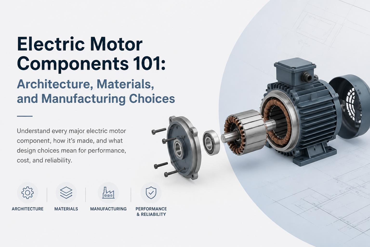
All rotary electric motors, from tiny fan drives to large industrial pumps, do the same basic job: convert electrical energy into mechanical torque on a shaft. To do that reliably, they combine four functional systems:
Magnetic circuit – stator and rotor laminations, magnetic cores, and airgap
Electrical circuit – copper (or aluminium) windings, conductors, and terminations
Mechanical structure – shaft, bearings, frame or housing, end shields, fan
Thermal and insulation system – insulation papers, varnish, impregnation, cooling paths
Different motor types (induction, brushless DC, universal, shaded pole, etc.) arrange and energize these systems differently, but the building blocks are consistent. Understanding these blocks is the first step to making better design and sourcing decisions.
2. Core magnetic components: stator, rotor, and laminations
The magnetic core is where most of the “motor physics” lives. It channels magnetic flux efficiently while minimizing losses. In modern motors, this is almost always a stack of thin electrical steel laminations.
2.1 Stator laminations
The stator is the stationary magnetic core that holds the main windings. Stator laminations are thin punched or laser-cut sheets of electrical steel, stacked and bonded to form the stator core.
Key design parameters:
Outer and inner diameter – sets frame size and rotor diameter
Slot number and shape – determines winding layout, harmonic content, and manufacturability
Stack length – major driver of torque and power capability
Tooth width and back iron thickness – balance between saturation margin and material cost
Stator laminations are typically produced using high-speed progressive die stamping for volume production, or laser cutting for prototypes and low-volume special machines.
For a deeper dive into geometry choices and their impact on losses and noise, see our guide to stator and rotor lamination design.
2.2 Rotor laminations
The rotor is the rotating magnetic core. Rotor laminations are similar to stator laminations but optimized for rotor construction (e.g., squirrel-cage bars in induction motors, interior magnets in some PM motors).
Typical rotor lamination features:
Rotor slots or bar slots – for cast aluminium or copper bars in induction motors
Magnet pockets – for surface-mounted or interior permanent magnets in brushless DC motors
Skew (implemented in the stack, not in a single lamination) – reduces cogging torque and acoustic noise
Central bore and keyway – for mounting on the shaft
Rotor laminations are stacked, then combined with either die-cast aluminium (induction motors), pressed-in magnets (BLDC and PM motors), or wound windings (wound-rotor machines).
2.3 Electrical steel grades and lamination thickness
Most motor laminations use non-oriented electrical steel (NOES) for rotating machines, with silicon content typically between 1.0–3.5%. Higher silicon content reduces core losses but can make the steel more brittle.
Key choices include:
Grade / loss class – lower-loss grades reduce iron losses and heating but cost more
Thickness – common thicknesses are 0.35 mm, 0.5 mm, and 0.65 mm; thinner laminations reduce eddy current losses, especially at higher frequencies
Coating – inorganic or organic coatings provide interlaminar insulation and impact stacking factor and punching performance
Standards such as IEC 60404 and ASTM A347/A347M (and related specs) describe properties and test methods for electrical steels.
2.4 Lamination manufacturing and annealing
How laminations are made has a direct impact on magnetic performance, dimensional accuracy, and cost. High-volume OEMs typically work with a specialized motor lamination manufacturer that offers:
Progressive die tooling for high-speed stamping
Precision stacking and interlocking methods
Stress-relief annealing to restore magnetic properties after punching
Punching introduces residual stresses that increase core losses. Proper heat treatment can significantly improve efficiency. Our article on annealing motor laminations explains typical furnace atmospheres, temperature profiles, and quality checks.
For a broader comparison of core options (laminated vs. solid vs. powder cores), see our overview of magnetic cores for electrical machines.
3. Electrical components: windings, conductors, and insulation
The electrical system energizes the magnetic circuit and carries current. It is a major driver of both performance and cost.
3.1 Stator windings
Stator windings can be made using round wire, rectangular wire, or pre-formed coils, depending on motor type and production volume.
Main options:
Random-wound coils – common in small motors and appliance drives; flexible and cost-effective
Form-wound coils – used in larger machines or where high voltage and reliability are critical
Hairpin windings – rectangular conductors bent into precise shapes, used in high-efficiency automotive and traction motors
Designers balance copper fill factor, ease of insertion, cooling, and manufacturability. Copper is still the norm for most motors, but aluminium windings are used in some cost-sensitive or weight-critical applications.
3.2 Rotor conductors and magnets
Rotor electrical components depend heavily on motor type:
Induction motors – cast aluminium (or copper) rotor bars and end rings form a squirrel cage. These are typically made by high-pressure die casting directly into the rotor lamination stack.
Brushless DC (BLDC) and permanent magnet synchronous motors (PMSM) – use rare-earth or ferrite magnets, either surface-mounted or embedded in the rotor laminations.
Universal and DC brushed motors – have wound rotors (armatures) with commutators and carbon brushes.
Magnet selection (NdFeB, ferrite, SmCo) impacts torque density, temperature capability, demagnetization risk, and cost. For many OEMs, securing a stable magnet supply chain is now a strategic concern.
3.3 Insulation system
The insulation system ensures dielectric integrity between turns, phases, and the core. It also plays a major role in thermal performance and lifetime.
Typical elements include:
Slot liners and wedges – insulating papers or laminates that protect wire from sharp lamination edges
Phase insulation – tapes and barriers between phase groups
Varnish / resin impregnation – vacuum pressure impregnation (VPI) or dip-and-bake processes that lock coils in place, improve heat transfer, and protect against moisture
Insulation systems are usually classified by thermal class (e.g., Class B 130°C, F 155°C, H 180°C) according to standards such as IEC 60085. Choosing a higher class can extend life at a given operating temperature or allow more aggressive thermal loading.
4. Mechanical components: shaft, bearings, and housing
Even a perfectly designed electromagnetic system will fail if the mechanical components cannot support loads, maintain alignment, or dissipate heat. Mechanical design is often where noise, vibration, and maintenance issues show up.
4.1 Shaft
The shaft transmits torque to the load and locates the rotor relative to the stator.
Key considerations:
Material – usually medium carbon steel; stainless or special alloys for corrosive or high-temperature environments
Diameter and length – sized for torque, bending, and critical speed; must also accommodate couplings, pulleys, or fan blades
Runout and concentricity – tight tolerances are essential for low vibration and bearing life
4.2 Bearings
Bearings support the rotating shaft and control radial and axial movement. They are critical to motor life and noise performance.
Common choices:
Deep groove ball bearings – standard in most small and medium motors
Roller bearings – for higher radial loads
Sleeve bearings – used in some fan and HVAC applications for low noise and cost
Factors like lubrication method (greased-for-life vs. relubricable), sealing, and bearing insulation (to prevent circulating currents in VFD-driven motors) must be specified carefully.
4.3 Frame, end shields, and covers
The motor frame or housing provides structural support, protection, and a thermal path to the environment. End shields or end bells hold the bearings and close the motor.
Manufacturing options include:
Cast iron or cast aluminium frames – robust, good heat dissipation; common in industrial motors
Sheet metal housings – lightweight and cost-effective, widely used in fans and small appliances
Die-cast components – allow integrated features (mounting feet, cooling fins, terminal boxes) with tight tolerances
Our overview of die-cast components for motors explains when aluminium die casting is a good fit and what OEMs should specify to avoid porosity and dimensional issues.
5. Thermal, cooling, and protection components
Thermal management is a major limiting factor in motor power density. Components and design features that manage heat include:
Cooling fan – mounted on the shaft to move air over the frame (TEFC motors) or through the motor (forced ventilation)
Fan cover / shroud – directs airflow and protects the fan; often a pressed sheet metal or moulded plastic component
Cooling fins – cast or machined into the frame to increase surface area
Embedded temperature sensors – PTC thermistors, RTDs, or thermal switches in the windings or core
For sealed or hazardous-area motors, additional features like water jackets, explosion-proof enclosures, or pressurized housings may be used.
6. Connection, control, and accessory components
How the motor connects to the power system and control electronics is increasingly important, especially in variable-speed and smart applications.
6.1 Terminal box and leads
The terminal box houses the connection points between stator windings and external cables. Its design must consider ingress protection (IP rating), ease of wiring, and strain relief.
Typical elements:
Terminal block or studs – for star/delta or other connection schemes
Cable glands – maintain IP rating while allowing entry of supply cables
Gaskets and seals – protect against dust and moisture
6.2 Sensors and feedback devices
Modern drives increasingly use feedback for precise speed and position control. Common accessories include:
Encoders – optical or magnetic, mounted on the shaft
Resolvers – for harsh environments
Hall sensors – in BLDC motors for commutation
6.3 Protection devices
Protection components can be embedded in the motor or installed externally:
Thermal switches – open at a set temperature
PTC thermistors – provide a steep resistance change near a threshold temperature
Overcurrent and ground fault protection – typically handled in the starter or drive, but must be compatible with motor insulation and construction
7. Architecture differences by motor type
While the building blocks are similar, different motor types emphasize different electric motor components. Understanding these differences helps you specify the right component set for each application.

7.1 Single phase induction motor components
Single phase induction motors are widely used in fans, pumps, compressors, and household appliances. Typical components include:
Stator and rotor laminations – similar to three-phase induction motors but optimized for single-phase operation
Main and auxiliary (start) windings – displaced in space to create a starting torque
Start capacitor and/or run capacitor – in capacitor-start or capacitor-run designs
Centrifugal switch or electronic relay – disconnects the start winding after run-up
Shaded poles or auxiliary poles – in shaded pole variants, copper shading coils provide phase shift without external capacitors
For ceiling fans and similar applications, component sets often include custom sheet metal covers, downrod brackets, and decorative elements in addition to the core electrical machine components.
7.2 Brushless DC motor components
Brushless DC (BLDC) motors use electronic commutation instead of brushes and a commutator. Their component set typically includes:
High-precision stator laminations – often with concentrated windings and small slot openings
Permanent magnet rotor – surface-mounted or interior magnets, sometimes overmoulded
Hall sensors or sensorless control capability – for rotor position detection
Integrated or separate electronic controller – power stage, gate drivers, and microcontroller
Because BLDC motors are usually used with variable-speed drives (fans, pumps, HVAC, appliances), electromagnetic design is closely tied to control strategy. Tight tolerances on laminations, magnets, and airgap are critical for low cogging and high efficiency.
7.3 Universal motor components
Universal motors run on both AC and DC and are common in power tools, mixers, and small appliances. Their key components are:
Laminated stator core with series field windings
Wound rotor (armature) with commutator segments
Carbon brushes and brush holders
High-speed bearings and balanced rotor – to handle very high RPM
Universal motors offer high power density and low cost but have higher noise and lower efficiency compared to induction or BLDC designs.
7.4 Shaded pole motor components
Shaded pole motors are simple, low-cost motors used in small fans, blowers, and low-power devices.
They typically include:
Stator laminations with salient poles
Copper shading coils around a portion of each pole
Squirrel-cage rotor similar to small induction motors
The absence of capacitors, switches, or complex control makes shaded pole motor components extremely cost-effective, but efficiency is relatively low.
8. Materials and manufacturing choices that move the needle
For OEMs, the most important decisions are rarely about exotic technologies. They are about choosing the right materials and manufacturing routes for your target performance and cost.
8.1 Magnetic materials and core manufacturing
Choices that significantly affect performance and price:
Electrical steel grade – higher-grade steels reduce core losses and heat but cost more and may require tighter process control.
Lamination thickness – thinner laminations improve high-frequency performance (important for high-speed or inverter-fed motors).
Punching vs. laser cutting – stamping with progressive dies offers low per-piece cost at volume; laser cutting is flexible and ideal for prototypes and smaller batches.
Annealing – proper annealing of motor laminations can recover magnetic properties lost during punching, improving efficiency by several percentage points.
8.2 Conductors and windings
Key trade-offs:
Copper vs. aluminium – copper offers higher conductivity and smaller motor size for the same output; aluminium reduces cost and weight but increases losses.
Random-wound vs. form-wound vs. hairpin – higher fill factors and better thermal paths improve efficiency but require more complex tooling and processes.
Automation level – automated winding and insertion improve consistency and reduce labour cost at scale.
8.3 Die-cast and sheet metal components
Frames, end shields, fans, and covers are often made using die casting or sheet metal fabrication. Choosing the right process affects both performance and aesthetics.
Aluminium die casting – ideal for integrated frames with cooling fins and mounting features. Our guide to die-cast components in motors explains design rules and common pitfalls.
Sheet metal components – cost-effective for fan covers, terminal box covers, and brackets, especially in ceiling fan and appliance motors.
9. Cost breakdown: where your motor budget really goes
In a typical small to medium-sized industrial motor, cost is dominated by materials, particularly copper and electrical steel. Labour, overhead, and machining make up the rest.

Typical ranges (very approximate, for illustration):
Laminations (stator + rotor) – 20–35% of material cost
Copper windings – 25–40%
Frame, end shields, covers – 10–20%
Bearings, shaft, hardware – 5–15%
Insulation and impregnation – 5–10%
This is why optimising lamination design and copper usage is so powerful: small percentage improvements in material utilization can deliver disproportionate savings over large production volumes.
10. What to look for in an electric motor component supplier
For OEMs, choosing the right partners for laminations, magnetic cores, and die-cast parts is as important as the motor design itself. Key evaluation criteria include:
Tooling and process capability – in-house tooling design, progressive die stamping, annealing furnaces, and die casting capability indicate a mature operation.
Material sourcing – established relationships with electrical steel mills, copper suppliers, and magnet manufacturers reduce supply risk.
Quality systems – adherence to standards such as ISO 9001 and robust in-process checks (dimensional, metallurgical, and magnetic testing).
Scale and flexibility – ability to support both development batches and high-volume production, with consistent on-time delivery.
According to industry analyses from organizations like the International Energy Agency, high-efficiency motors can reduce industrial electricity use significantly. That efficiency depends heavily on lamination quality, magnetic materials, and manufacturing processes – all areas where a capable component partner adds value.
11. Bringing it all together
Electric motor components are not interchangeable commodities. Choices around lamination design, steel grade, winding technology, die-cast structures, and insulation systems all interact to determine efficiency, noise, size, and lifetime cost.
For OEMs and engineering teams, the most effective approach is to treat component suppliers as technical partners, not just vendors. Involve them early in design, especially for stator and rotor laminations, magnetic cores, and die-cast parts. Align on performance targets, manufacturability, and total cost of ownership rather than just unit price.
When you understand how each component contributes to the whole, you can specify smarter, ask better questions, and ultimately build motors that are more efficient, reliable, and competitive in the market.