When you specify magnetic cores for a new motor design, you are locking in a big part of its efficiency, noise, and cost long before the first prototype spins. Yet many design teams only see the final stator core and rotor core, not the manufacturing, annealing, and testing steps that determine how those cores behave in the real world.
This explainer walks through how magnetic cores for electric motors are actually made, what drives core losses, and how serious suppliers test every batch. With a clearer view of motor core manufacturing, you can write better specifications, ask sharper questions, and choose partners who can really deliver the performance you are designing for.
If you are new to electrical stamping, it can help to first review the basics of electrical stamping for motor laminations, since stamping quality underpins everything we cover here.
What is a magnetic core in an electric motor?
In an electric motor, the magnetic core is the laminated steel structure that guides magnetic flux between stator and rotor. It is built from thin electrical steel sheets (laminations) stacked together to form:
Stator core – the stationary ring with slots for windings
Rotor core – the rotating stack, often with bars or a die-cast cage
Using thin insulated laminations instead of a solid steel block is what keeps eddy current losses under control at AC frequencies. The choice of electrical steel grade, lamination thickness, and manufacturing route directly affects:
Core losses (watts per kilogram)
Efficiency and temperature rise
Noise and vibration
Torque density and power factor
Cost and manufacturability at volume
From coil to core: overview of motor core manufacturing
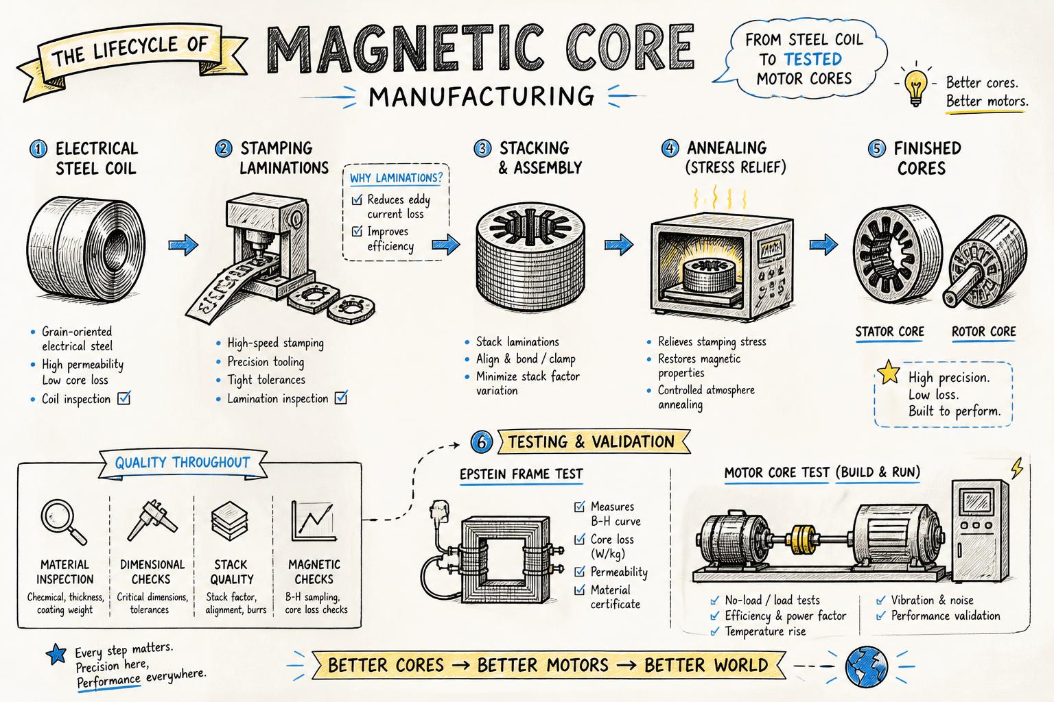
Although every supplier has its own process details, most magnetic core manufacturing for motors follows the same sequence:
Select and slit the electrical steel coil
Stamp laminations for stator and rotor
Stack and interlock, weld, or bond the laminations into cores
Anneal the cores to restore magnetic properties
Test core losses and magnetic performance
Each step can either preserve the steel maker’s published loss values or degrade them. Understanding where things go wrong helps you write requirements that protect your design targets.
For a deeper dive into how lamination geometry and slot design affect performance, see our guide to designing rotor and stator laminations for high-efficiency motors.
Step 1: Choosing electrical steel grades for magnetic cores
The starting point is the electrical steel itself. Broadly, motor cores for industrial and appliance applications use:
Non-oriented electrical steel (NOES) – isotropic magnetic properties, common in rotating machines
Grain-oriented electrical steel (GOES) – optimized in the rolling direction, mainly for transformers rather than motors
Within NOES there are multiple grades, typically characterized by:
Core loss at a reference point (for example at 1.5 T, 50/60 Hz, W/kg)
Lamination thickness (for example 0.35 mm, 0.5 mm)
Yield strength and hardness (affects stamping behaviour and burr formation)
Coating type (insulation, punchability, weldability)
Higher-grade steels usually offer lower core losses but may cost more and require tighter control of stamping and annealing to realize their potential. Standards such as ISO 23526 for non-oriented electrical steel and IEC 60404 series define how these properties are measured.
What to specify as a motor designer
Instead of naming only a commercial trade name, it is more robust to specify:
Maximum core loss at your relevant flux density and frequency (for example < 3.0 W/kg at 1.5 T, 50 Hz)
Maximum lamination thickness and burr height
Required coating class (for example inorganic, weldable coating)
Mechanical properties if your design is sensitive to distortion
Then confirm with your stamping partner how they will verify these properties on incoming coils and maintain traceability through to finished cores.
Step 2: Stamping laminations without destroying the steel
Once the coil is selected and slit, laminations are stamped using either simple tools or high-speed progressive dies. Poor tool design or maintenance can introduce residual stresses, large burrs, and deformation that increase core losses beyond what the mill data sheet suggests.
Key stamping factors for low-loss magnetic cores include:
Sharp, well-maintained tooling – minimizes plastic deformation and work hardening at the cut edge
Appropriate clearance between punch and die – too small increases force and stress, too large increases burrs
Controlled press tonnage and speed – matched to part size, thickness, and material properties
Good strip support and guiding – to avoid micro-cracking and distortion
For high-volume OEM programs, progressive die stamping for motor components often delivers the best balance of dimensional control, speed, and cost per part, provided the die is designed with electrical steel behaviour in mind.
Burrs, edge damage, and their impact on core losses
Burrs and damaged edges reduce the effective insulation between laminations and create local shorted turns, which increase eddy current losses. Excessive burrs also complicate stacking and can cause mechanical interference with windings.
Typical motor specifications limit burr height to a fraction of the lamination thickness (for example < 10% of thickness). It is good practice to define both a maximum burr height and the measurement method so your supplier’s inspection matches yours.
Step 3: Building the stator core and rotor core
After stamping, laminations are converted into stator and rotor cores by stacking and joining. Common techniques include:
Interlocking or cleating – features in the lamination lock together when pressed
Welding – usually TIG or laser welds on the outer diameter or end faces
Bonding – using adhesive-coated steel or post-stacking bonding processes
Each method has trade-offs in cost, mechanical robustness, and impact on magnetic performance:
Interlocking is fast and low-cost but can introduce localized deformation
Welding adds heat-affected zones that must be considered in annealing
Bonded cores can offer excellent loss performance and low noise but add process complexity
Rotor cores for induction motors may then proceed to die casting, where aluminium is cast into the rotor slots and end rings. The thermal cycle of die casting interacts with prior annealing, so your core manufacturing and die casting partners must coordinate process windows.
For appliance and HVAC applications, where sheet metal parts and motor components come together, it is often efficient to work with a supplier experienced in both sheet metal components for electrical appliances and motor laminations, to simplify interfaces between brackets, housings, and cores.
Step 4: Annealing services – restoring magnetic properties
Stamping and stacking introduce mechanical stresses that degrade magnetic performance. Annealing is a controlled heat treatment that relieves these stresses and, when done correctly, brings the core’s losses close to the steel maker’s reference values.
Typical annealing for non-oriented electrical steel involves:
Heating to a specific temperature range (often 700–850 °C, depending on grade)
Holding for a defined soak time to allow stress relief and grain growth
Cooling at a controlled rate to avoid new stresses or coating damage
Using a protective atmosphere (for example nitrogen, hydrogen mix) to prevent oxidation
The exact cycle must follow the steel producer’s recommendations and be validated by loss measurements before and after annealing. Poorly controlled annealing can lead to:
Incomplete stress relief (higher core losses than expected)
Coating degradation and increased inter-laminar shorting
Distortion of the core, affecting air gap and fit with housings
When you evaluate annealing services, ask how furnace temperature is monitored, how atmosphere composition is controlled, and how often they correlate process parameters with magnetic testing.
Understanding core losses: hysteresis, eddy currents, and excess loss
Core losses in magnetic cores are usually broken into three components:
Hysteresis loss – energy lost each time the material is magnetized and demagnetized, proportional to frequency and the area of the B-H loop
Eddy current loss – currents induced in the steel by changing flux, proportional to frequency squared, lamination thickness squared, and inversely to resistivity
Excess or anomalous loss – associated with domain wall motion and microstructural effects
Reducing core losses is a combination of material choice (grade, thickness, coating) and process control (stamping, stacking, annealing). A study summarized in IEEE publications on electrical steel processing shows that poor punching can increase losses by 10–30% compared with carefully optimized conditions, even with the same steel grade.
How electrical steel grade affects losses
Higher-grade NOES usually has a more favourable microstructure and lower impurity content, which reduces hysteresis and eddy current components at a given flux density. The benefit is visible when you compare W/kg values across grades at the same test point.
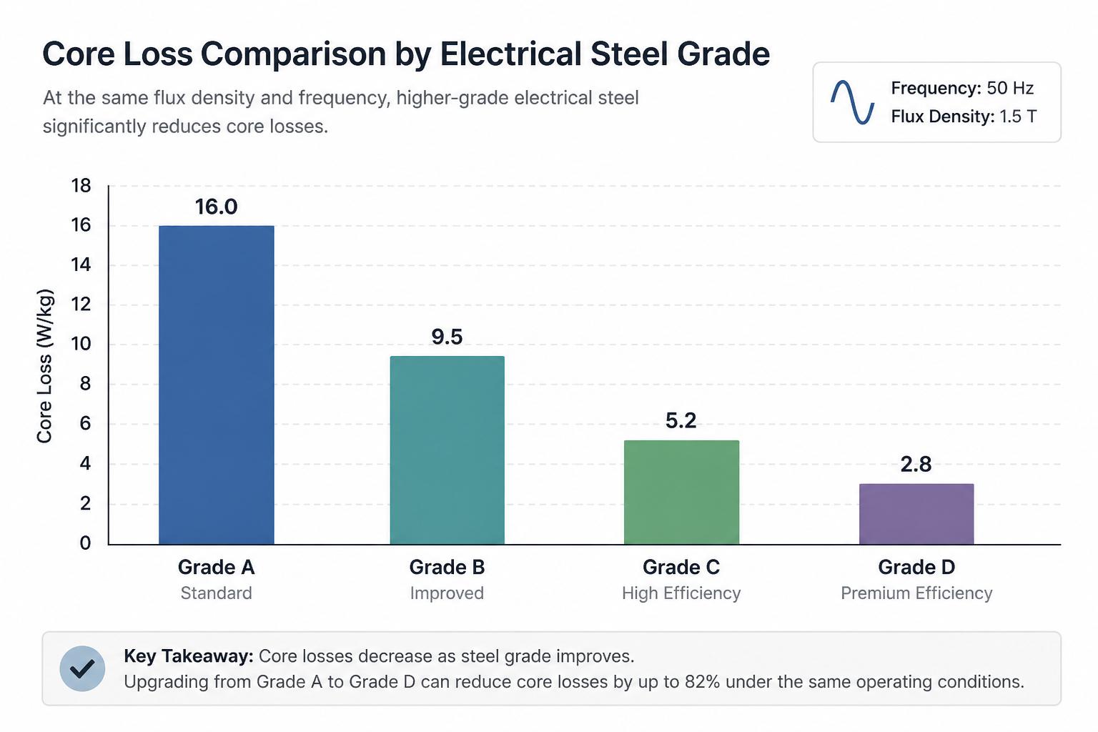
In practice, you should always combine mill data with core loss measurements on your actual stator core and rotor core, because geometry, stress, and assembly all influence the final result.
How magnetic cores are tested: Epstein testing and beyond
Reliable testing is what connects your design assumptions to real-world performance. For motor core manufacturing, three levels of testing are common:
Material-level testing – on strips or samples from the coil
Core-level testing – on finished stator and rotor stacks
Motor-level testing – on complete motors under load
Epstein testing of electrical steel and cores
The classic method for characterizing electrical steel is the Epstein frame, standardized in IEC 60404-2. Strips of steel are assembled into a square magnetic path and excited at defined flux densities and frequencies to measure:
While Epstein testing is often performed by steel mills, advanced motor component suppliers also use Epstein testing on stamped and annealed laminations to see how their process affects loss compared with the raw material. This is particularly important when optimizing annealing cycles or changing tooling.
Core testing on finished stator and rotor stacks
Beyond Epstein frames, there are test setups that energize the actual stator core or rotor core to measure:
Core loss at different flux densities and frequencies
Excitation current versus voltage
Localized hot spots due to assembly defects
Some OEMs specify maximum allowable loss for a finished stator at a defined test condition. This forces the manufacturing process (stamping, stacking, annealing) to be tuned until the finished core meets the same level of performance assumed in electromagnetic simulations.
Motor-level validation
Ultimately, core performance shows up as:
Efficiency and power factor versus load
Temperature rise of stator and rotor
Audible noise and vibration
Industry standards such as IEC 60034 for rotating electrical machines define many of these test methods. When you see unexpected losses or heating in motor tests, it is often worth going back to core-level testing to distinguish between magnetic and copper or mechanical contributions.
Design and manufacturing choices that reduce core losses
Once you understand where losses come from, you can make targeted decisions in both design and manufacturing. Some practical levers include:
1. Optimize lamination thickness
Thinner laminations reduce eddy current losses but may increase cost and complicate stamping. For many appliance and industrial motors, 0.35 mm or 0.5 mm NOES is a good compromise. High-speed or high-frequency machines may justify even thinner gauges.
2. Control flux density in critical regions
Avoid pushing flux density too close to saturation in teeth, yokes, or rotor bridges. Local saturation not only increases hysteresis loss but can also create strong local forces that drive noise. Slot geometry, tooth width, and air-gap design all play a role here, as discussed in our article on lamination design for high-efficiency motors.
3. Specify and monitor burr limits
Include clear burr height limits and inspection plans in your drawings and quality agreements. Ask your supplier how they maintain tool sharpness and how often they measure burrs across the strip width and tool life.
4. Validate annealing parameters with data
Rather than treating annealing as a black box, request before-and-after loss measurements on representative cores when setting up a new program. Once a stable process window is defined, lock it into the control plan and audit it periodically.
5. Align core manufacturing with downstream processes
Processes such as die casting of rotors, impregnation, or assembly into sheet metal housings can introduce new stresses or thermal cycles. Co-designing these interfaces with a supplier experienced in motor stamping and die casting for OEMs helps preserve the low-loss performance you paid for in the steel.
What to look for in a magnetic core manufacturing partner
For OEMs, the practical question is not just “what is the best steel grade?” but “which supplier can repeatedly deliver magnetic cores that hit my loss, cost, and delivery targets?” Key capabilities to look for include:
In-house tooling design and maintenance – to control burrs, dimensional accuracy, and tool life
High-tonnage, well-maintained presses – matched to your lamination sizes and volumes
Proven annealing services – with documented furnace control, atmosphere management, and correlation to loss data
Magnetic testing capability – such as Epstein testing and core loss testing on finished stacks
Integrated processes – die casting, CNC machining, and sheet metal fabrication where relevant
ISO-certified quality systems – with SPC, traceability, and robust incoming and final inspection
Suppliers like ASA Industries combine electrical stamping, magnetic core manufacturing, annealing, and testing under one roof, which simplifies process control and reduces the risk of performance drift between prototype and mass production.
How to specify magnetic cores in your next motor project
To close, here is a concise checklist you can adapt for your own drawings and purchase specifications:
By treating magnetic cores as a tightly controlled, test-backed component rather than a commodity stamping, you can unlock meaningful gains in efficiency, reliability, and total cost of ownership across your motor portfolio.